Control system and method for a liquid desiccant air delivery system

a control system and liquid desiccant technology, applied in the field of air delivery systems, can solve the problems of inability of desiccant-based hvac energy exchange systems to process liquid desiccant to maintain supply air conditions, and the need for auxiliary energy for conditioning the supply air typically requires a significant amount of auxiliary energy

Active Publication Date: 2014-09-18
NORTEK AIR SOLUTIONS CANADA INC
View PDF15 Cites 89 Cited by
  • Summary
  • Abstract
  • Description
  • Claims
  • Application Information

AI Technical Summary

Problems solved by technology

Without energy recovery, conditioning the supply air typically requires a significant amount of auxiliary energy, particularly in environments having extreme outside air conditions that are much different than the required supply air temperature and humidity.
However, known desiccant-based HVAC energy exchange systems lack processes for conditioning the liquid desiccant to maintain supply air conditions.

Method used


Image

  • Control system and method for a liquid desiccant air delivery system
  • Control system and method for a liquid desiccant air delivery system
  • Control system and method for a liquid desiccant air delivery system

Examples


Embodiment Construction

[0050]The foregoing summary, as well as the following detailed description of certain embodiments will be better understood when read in conjunction with the appended drawings. As used herein, an element or step recited in the singular and proceeded with the word “a” or “an” should be understood as not excluding plural of the elements or steps, unless such exclusion is explicitly stated. Furthermore, references to “one embodiment” are not intended to be interpreted as excluding the existence of additional embodiments that also incorporate the recited features. Moreover, unless explicitly stated to the contrary, embodiments “comprising” or “having” an element or a plurality of elements having a particular property may include additional such elements not having that property.

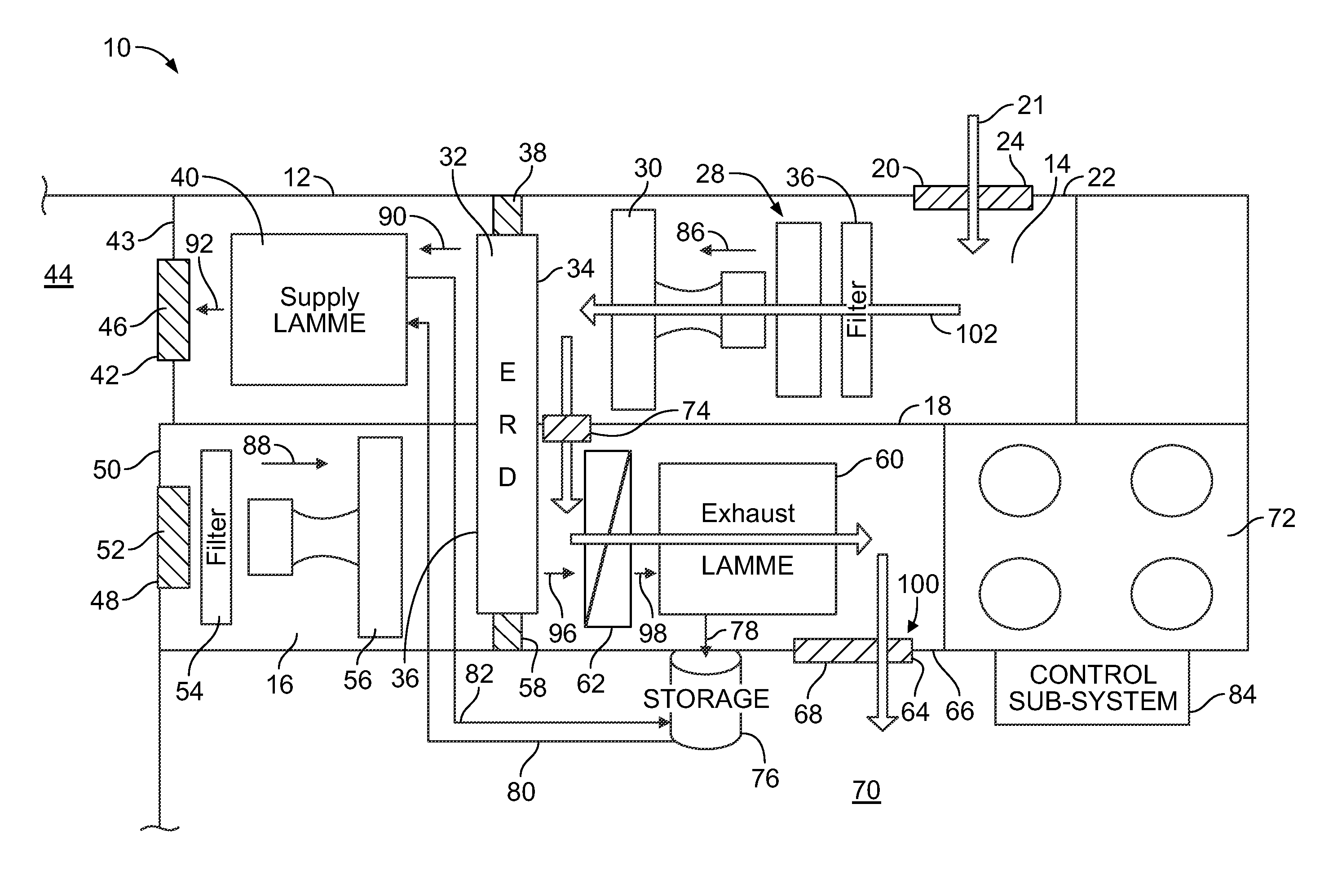
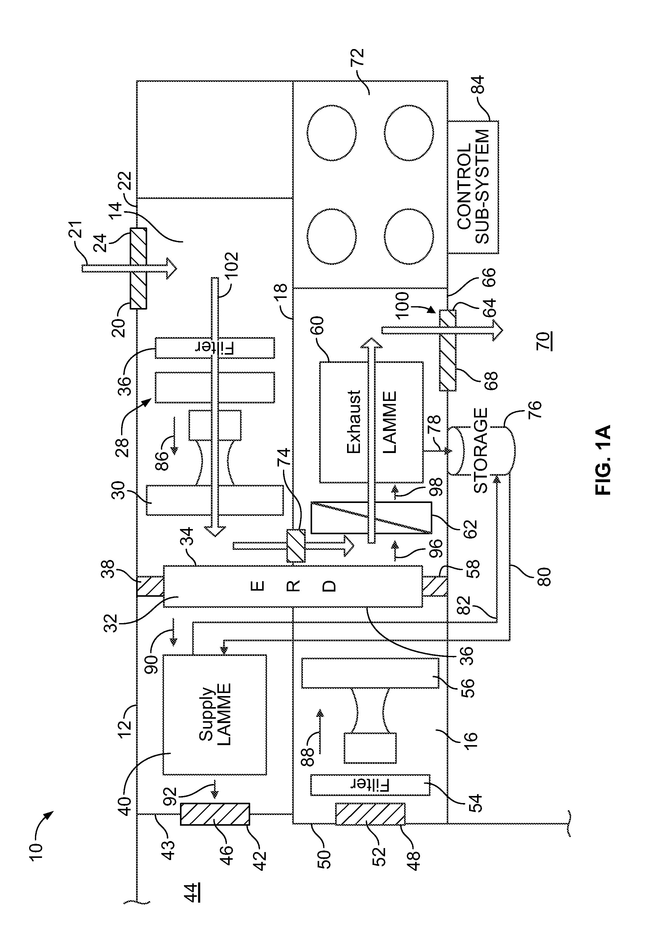
[0051]FIG. 1A illustrates a schematic view of an air delivery system 10, according to an embodiment of the present disclosure. The air delivery system 10 includes a housing 12, such as a cabinet, which may includ...


PUM


Abstract

An air delivery system may include a housing, a first liquid-to-air membrane energy exchanger (LAMEE), and a desiccant storage tank. The housing includes a supply air channel and an exhaust air channel. The first LAMEE may be an exhaust LAMEE disposed within an exhaust air channel of the housing. The exhaust LAMEE is configured to receive the outside air during a desiccant regeneration mode in order to regenerate desiccant within the exhaust LAMEE. The desiccant storage tank is in communication with the exhaust LAMEE. The exhaust LAMEE is configured to store regenerated desiccant within the desiccant storage tank. The regenerated desiccant within the desiccant storage tank is configured to be tapped during a normal operation mode.

Description

CROSS-REFERENCE TO RELATED APPLICATIONS[0001]The present application relates to and claims priority benefits from U.S. Provisional Patent Application No. 61 / 793,826, entitled “Method and System for Maintaining Supply Air Conditions in an Energy Exchange System,” filed Mar. 15, 2013, which is hereby expressly incorporated by reference in its entirety.BACKGROUND OF THE DISCLOSURE[0002]Embodiments of the present disclosure generally relate to air delivery systems, such as HVAC, air handling, heat pump, and energy exchange systems, and, more particularly, to control systems and methods for air delivery systems.[0003]Enclosed structures, such as occupied buildings, factories and the like, generally include a heating / ventilation / air conditioning (HVAC) system for conditioning outdoor ventilated and / or recirculated air. The HVAC system typically includes a supply air flow path and an exhaust air flow path. The supply air flow path receives pre-conditioned air, for example outside air or ou...

Claims


Application Information

Patent Timeline
Patent Type & Authority Applications(United States)
IPC IPC(8): F24F3/14
CPCF24F3/1417F24F3/147F24F12/002F24F2003/1435Y02B30/56Y02B30/52F24F2003/1464F24F2012/007
Inventor COUTU, KENNETH PAULFORMAN, CAMLEPOUDRE, PHILIP PAULERB, BLAKE NORMANHEMINGSON, HOWARD BRIANGERBER, MANFRED
Owner NORTEK AIR SOLUTIONS CANADA INC
Why Eureka
Try Eureka