Expansion Valve and Vibration-Proof Spring
a technology of expansion valve and vibration-proof spring, which is applied in the direction of shock absorbers, machine supports, lighting and heating apparatus, etc., can solve the problems of difficult to control the vibration of the shaft, the load between the first plate spring and the sliding load is more likely to be lost, and the assembly work is longer and complicated, so as to suppress the load applied, the effect of easy assembling work of the vibration-proof spring
- Summary
- Abstract
- Description
- Claims
- Application Information
AI Technical Summary
Benefits of technology
Problems solved by technology
Method used
Image
Examples
first embodiment
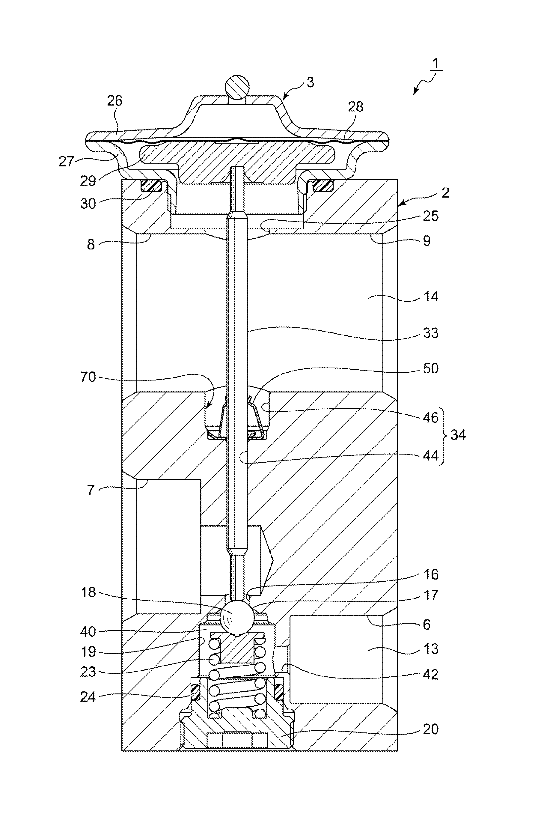
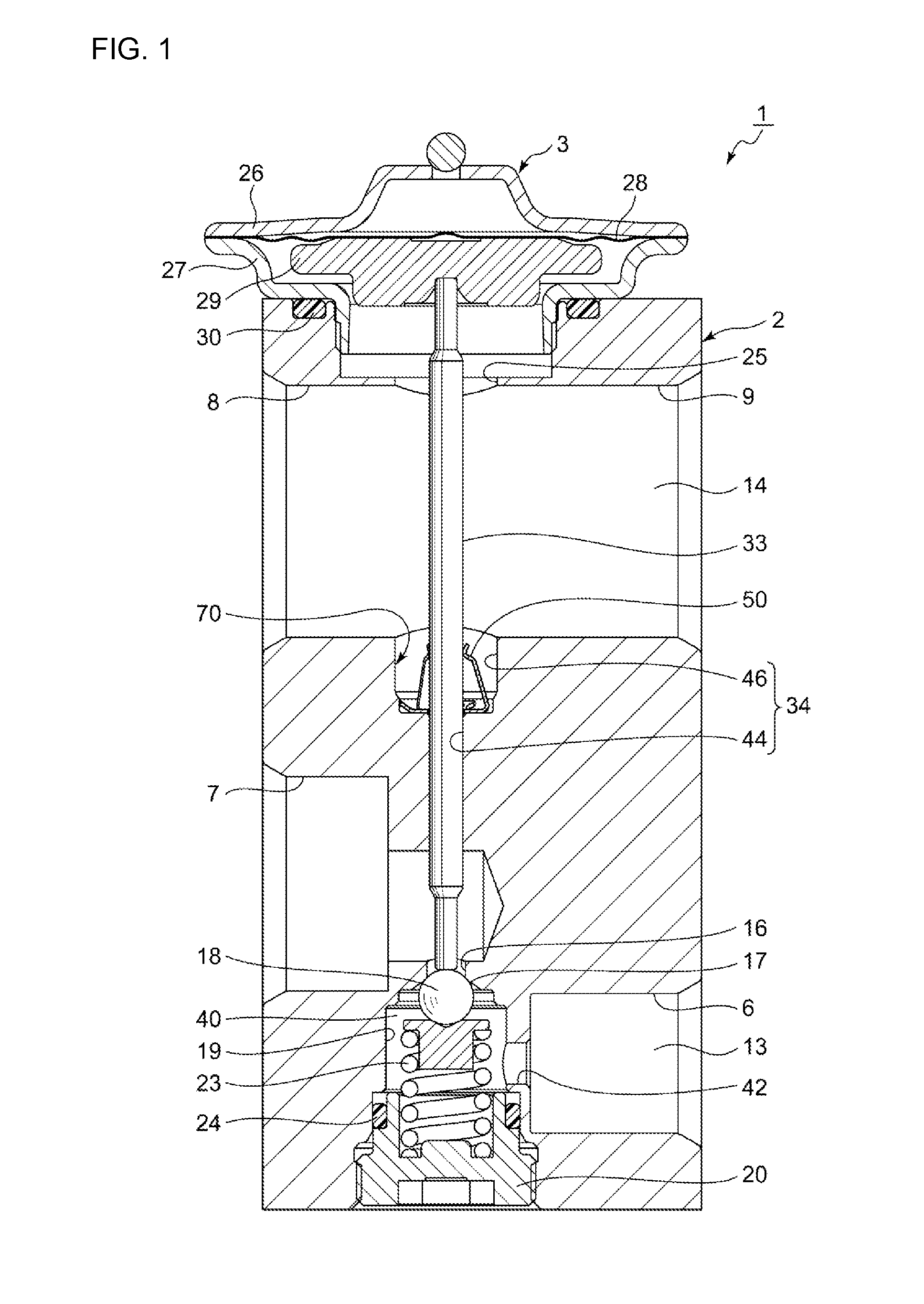
[0025]The present embodiment is a constructive reduction to practice of the present invention where an expansion valve according to the preferred embodiments is used in a specific manner as a thermostatic expansion valve applied to a refrigeration cycle of an automotive air conditioner. The refrigeration cycle in the automotive air conditioner is configured by including a compressor, a condenser, a receiver, an expansion valve, and an evaporator. Here, the compressor compresses a circulating refrigerant; the condenser condenses the compressed refrigerant; the receiver separates the condensed refrigerant into a gas and a liquid; the expansion valve throttles and expands the separated liquid refrigerant and delivers it by turning it into a spray; the evaporator evaporates the misty refrigerant and thereby cools the air inside a vehicle by the evaporative latent heat. Note that a detailed description of components except for the expansion valve is omitted in the following.
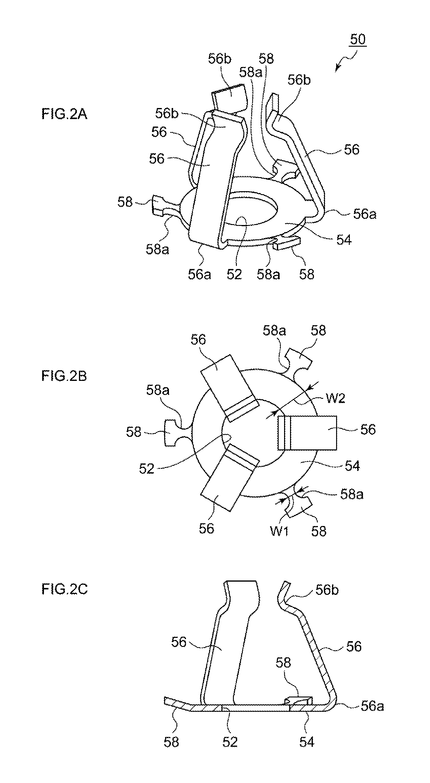
[0026]FIG. 1 ...
second embodiment
[0052]An expansion valve according to a second embodiment is similar to the first embodiment in structure and arrangement excepting that a structure of the low-rigidity portion of the supporting piece in the vibration-proof spring according to the second embodiment differs from that of the first embodiment. FIG. 4A is a perspective view showing an overall structure of a vibration-proof spring 150 according to the second embodiment. FIG. 4B is a plain view of the vibration-proof spring 150. FIG. 4C is a cross-sectional view of the vibration-proof spring 150. A basic function of the vibration-proof spring 150 according to the second embodiment is the same as the function of the vibration-proof spring 50 according to the first embodiment. Thus, the reference numerals of corresponding components in the second embodiment are replaced by 3-digit reference numerals where 100 is added to each reference numeral used in the first embodiment, and the repeated description thereof is omitted. Fo...
third embodiment
[0055]An expansion valve according to a third embodiment is similar to the first and second embodiments in structure and arrangement excepting that a structure of the low-rigidity portion of the supporting piece in the vibration-proof spring according to the third embodiment differs from those of the first and second embodiments. FIG. 5A is a perspective view showing an overall structure of a vibration-proof spring 250 according to the third embodiment. FIG. 5B is a plain view of the vibration-proof spring 250. FIG. 5C is a cross-sectional view of the vibration-proof spring 250.
[0056]The vibration-proof spring 250 shown in FIGS. 5A to 5C is achieved such that a low-rigidity portion 258a of the supporting piece 258 is formed by forming a notch (cutout section), which extends in a direction where a supporting piece 258 extends. Thus, two supporting pieces are formed. The plate width of each of the two supporting pieces perpendicular to the direction of extension thereof is narrower th...
PUM
 Abstract
Description
Claims
Application Information
 - R&D
- Intellectual Property
- Life Sciences
- Materials
- Tech Scout
- Unparalleled Data Quality
- Higher Quality Content
- 60% Fewer Hallucinations
Browse by: Latest US Patents, China's latest patents, Technical Efficacy Thesaurus, Application Domain, Technology Topic, Popular Technical Reports.
© 2025 PatSnap. All rights reserved.Legal|Privacy policy|Modern Slavery Act Transparency Statement|Sitemap|About US| Contact US: help@patsnap.com


