
Suspension device

a suspension device and splint technology, applied in the direction of shock absorbers, gearing, transportation and packaging, etc., can solve the problem of deviation of the axis of the ball screw, and achieve the effect of suppressing the load applied

Pending Publication Date: 2022-10-06
HONDA MOTOR CO LTD
View PDF37 Cites 0 Cited by
  • Summary
  • Abstract
  • Description
  • Claims
  • Application Information

AI Technical Summary

Benefits of technology

The patent invention aims to fix a problem where the rotation of a ball screw causes torque, which loosens the fixing of the fixing member, which in turn causes the axis of the ball screw to deviation. This invention likes to prevent the load caused by the axis deviation of the ball screw.

Problems solved by technology

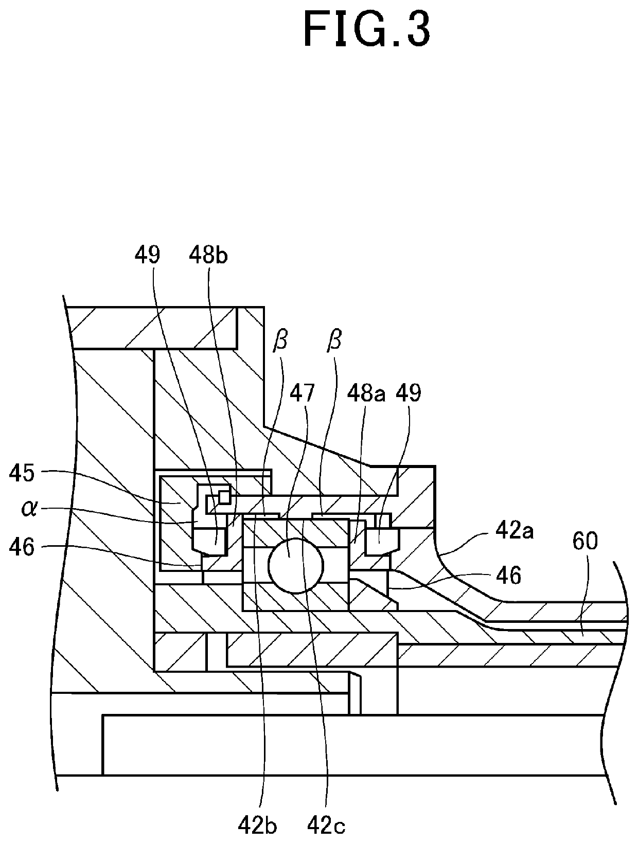
In that case, a problem arises such that: the torque based on the rotation of the ball screw is transmitted to the fixing member to loosen the fixing of the fixing member; and this deviates the axis of the ball screw, and this axis deviation applies a load.

Method used


Image

  • Suspension device
  • Suspension device
  • Suspension device

Examples


Embodiment Construction

[0017]The following describes a suspension device according to the present invention in detail with suitable embodiments with reference to the attached drawings.

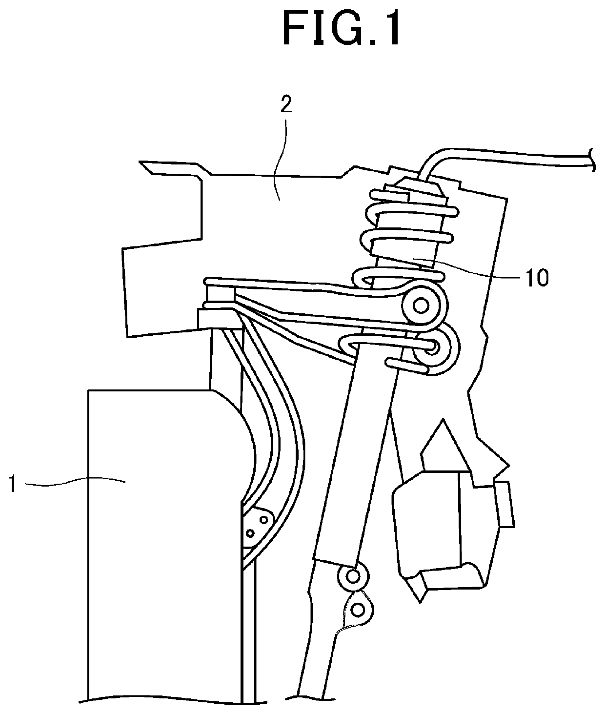
[0018]FIG. 1 is a diagram showing an example of mounting the suspension device 10 according to this embodiment on a vehicle. The suspension device 10 is configured as an external force mitigation device of a vehicle. The suspension device 10 is provided between a vehicle body 2 and wheels 1 to mitigate external force including vibration and impact from unevenness of the road surface, and improves ride quality, steering stability, etc. by pressing the wheel 1 against the road surface. Note that where to install the suspension device 10 is not limited to a vehicle, and the suspension device 10 can be applied to any part as a vibration damping device for suppressing vibration, for example.

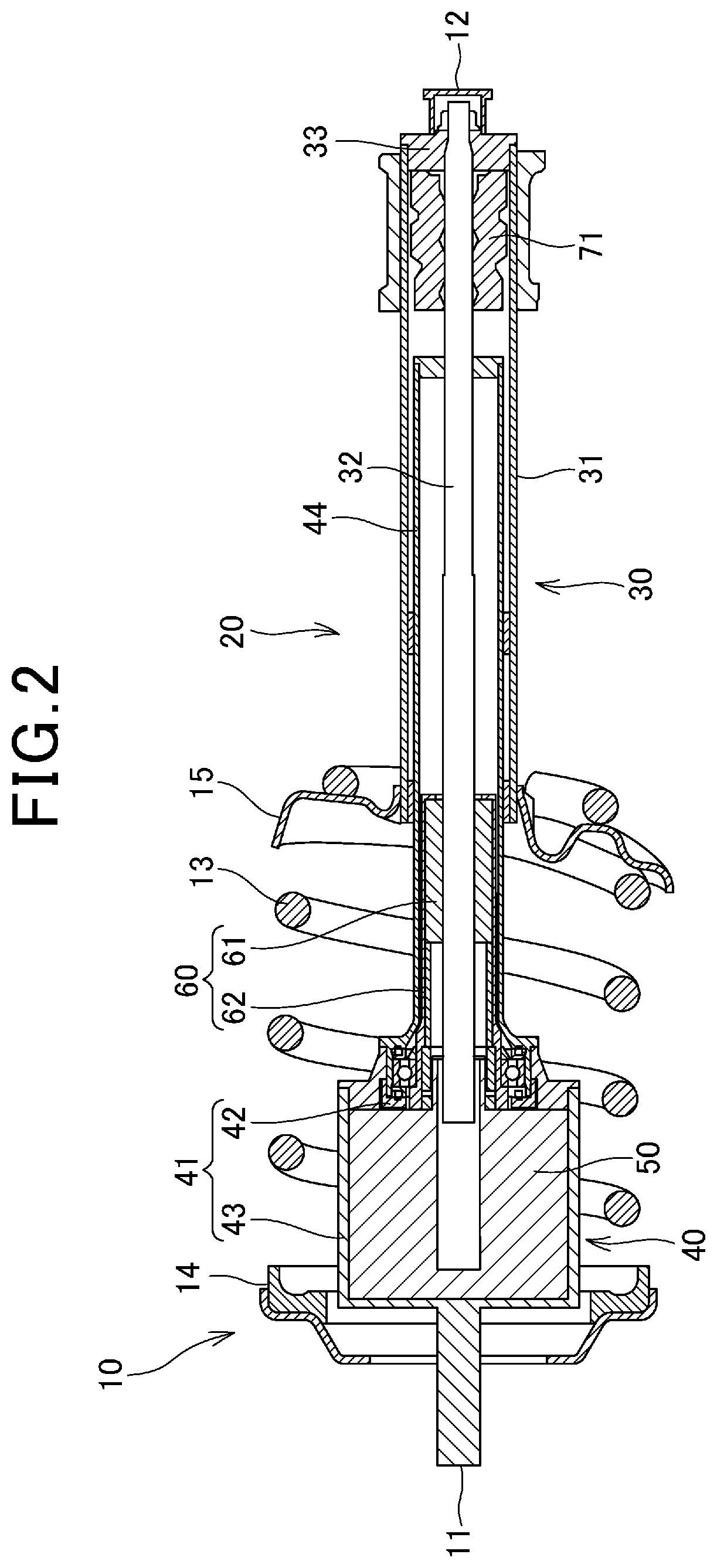
[0019]FIG. 2 is a schematic cross-sectional view in an axial direction of the suspension device 10. The suspension device 10 has a structure ...


PUM


Abstract

A suspension device includes a damper. The damper includes: an outer cylinder; a ball screw housed in the outer cylinder; a fastening member that supports the ball screw inserted therethrough and is attached to an end part of the outer cylinder; and a fixing member that is attached to an end part of the ball screw and fixes the ball screw to the fastening member. An insertion portion, where the ball screw is inserted into the fastening member, is provided with a fitting portion where the ball screw fits the fastening member, and the fitting portion has a spline fitting structure.

Description

INCORPORATION BY REFERENCE[0001]The present application claims priority under 35 U.S.C.§ 119 to Japanese Patent Application No. 2021-057361 filed on Mar. 30, 2021. The content of the application is incorporated herein by reference in its entirety.BACKGROUND OF THE INVENTIONField of the Invention[0002]The present invention relates to a suspension device.Description of the Related Art[0003]Suspension devices are applied to vehicles, for example, to damp vibration and impact applied to the vehicle and improve ride quality. In recent years, as a suspension device of this type, a suspension device including a nut screwed with a screw shaft portion and generating damping force by the electromagnetic action of a motor has been developed (see, for example, Japanese Patent Laid-Open No. 2016-17535). In the suspension device disclosed in Japanese Patent Laid-Open No. 2016-17535, when a nut receives a load from the outside and the nut moves straight, the screw shaft portion rotates. When the s...

Claims


Application Information

Patent Timeline
Patent Type & Authority Applications(United States)
IPC IPC(8): B60G17/02B60G13/08B60G15/06B60G17/015
CPCB60G17/021B60G13/08B60G15/065B60G17/0157B60G2202/312B60G2202/32B60G2202/42F16F15/022F16F7/00F16F9/3207F16H25/2204B60G13/16B60G2202/25B60G15/067B60G2204/128B60G2204/418B60G2206/41F16C2326/05F16C19/06F16C25/083F16F15/03F16F2232/06F16F9/3242
Inventor KUBOTA, KOHEIMASUBUCHI, TAKEHITO
Owner HONDA MOTOR CO LTD
Learn More