
Seal structure for multi-cylinder internal combustion engine

Inactive Publication Date: 2005-03-03
TOYOTA JIDOSHA KK
View PDF4 Cites 4 Cited by
  • Summary
  • Abstract
  • Description
  • Claims
  • Application Information

AI Technical Summary

Benefits of technology

[0012] According to the first aspect, by providing the above-mentioned seal portions whose forms are different from each other, it is possible to appropriately apply the same load to the periphery of the internal surface of each of all the cylinders, while suppressing variation in the loads applied to the cylinders. Namely, it is possible to appropriately suppress the load applied to the periphery of the internal surface of each of the cylinders other than the cylinders at both ends of the cylinder alignment from being smaller than the load applied to the periphery of the internal surface of each of the cylinders at both ends of the cylinder alignment in the cylinder block. Therefore, the structure of the internal combustion engine can be appropriately maintained, for example, reduction in coaxiality among bearings for a crank journal due to variation in the loads can be appropriately suppressed. Accordingly, with the above-mentioned structure, it is possible to provide sealing between the cylinder block and the cylinder head more appropriately.
[0031] According to the fifth aspect, by providing the compensating means, it is possible to apply the load to the periphery of the internal surface of each of all the cylinders more appropriately, while suppressing variation in the loads applied to the cylinders. Namely, it is possible to appropriately suppress the load applied to the periphery of the internal surface of the cylinder by the bolt from decreasing as the number of the cylinders adjacent to the bolt increases. Therefore, the structure of the internal combustion engine can be appropriately maintained, for example, reduction in coaxiality among bearings for the crank journal due to variation in the loads can be appropriately suppressed. Accordingly, with the above-mentioned structure, it is possible to provide sealing between the cylinder block and the cylinder head more appropriately.

Problems solved by technology

However, even when such adjustment is made, there is a possibility that coaxiality among bearings for a crank journal of the cylinder block is reduced.
Also, reduction in coaxiality among the bearings may result in an increase in the friction between the crank journal and the bearings therefor, seizing up of the bearing, and the like.
Accordingly, with the conventional seal structure for an internal combustion engine, it is difficult to achieve both provision of sealing between the cylinder block and the cylinder head, and maintenance of the structure of an internal combustion engine in an appropriate state.

Method used


Image

  • Seal structure for multi-cylinder internal combustion engine
  • Seal structure for multi-cylinder internal combustion engine
  • Seal structure for multi-cylinder internal combustion engine

Examples


Embodiment Construction

[0035] Hereafter, an embodiment, in which a seal structure for a multi-cylinder internal combustion engine according to the invention is applied to a seal structure for an in-line four-cylinder internal combustion engine, will be described with reference to accompanying drawings.

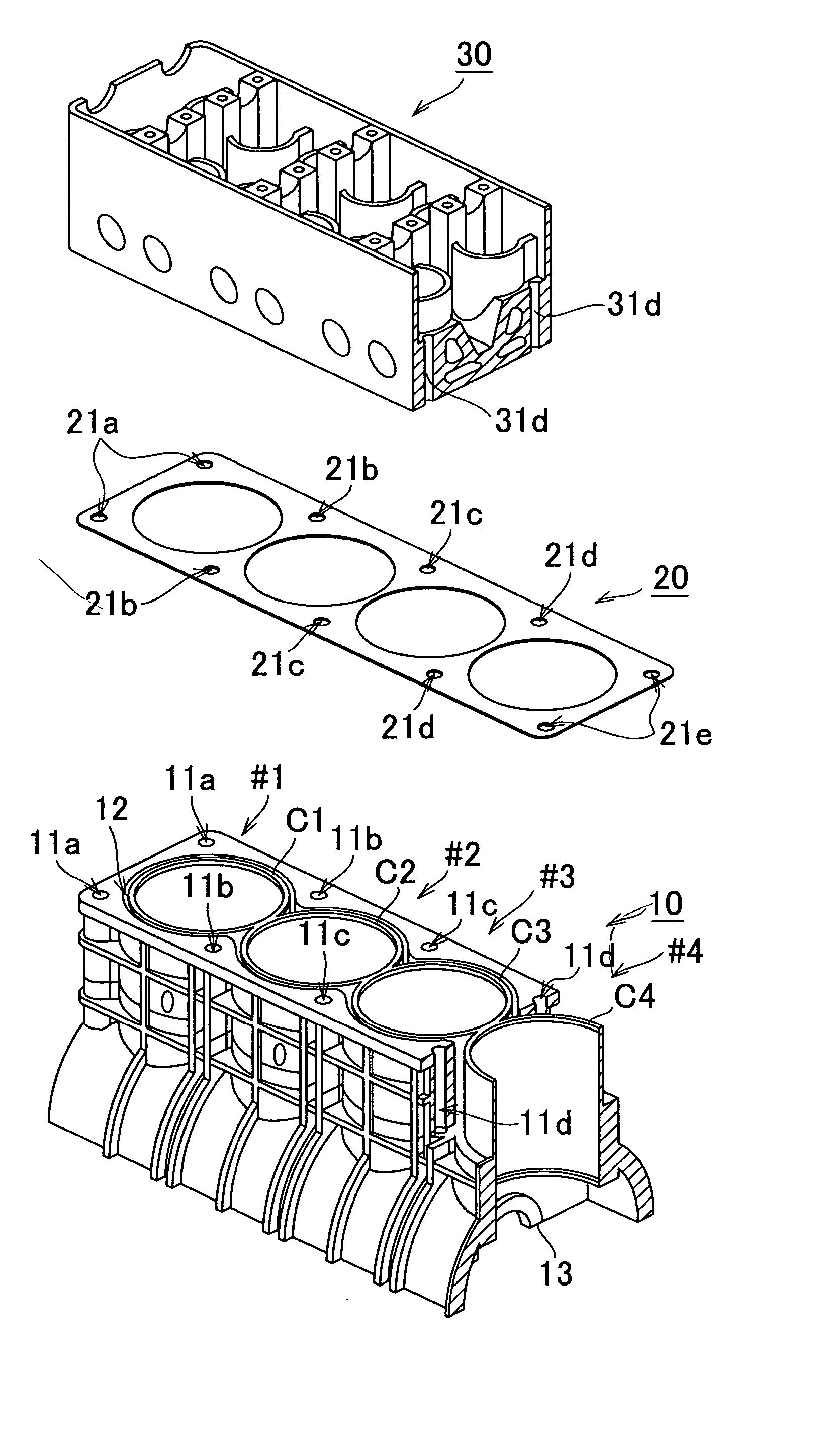
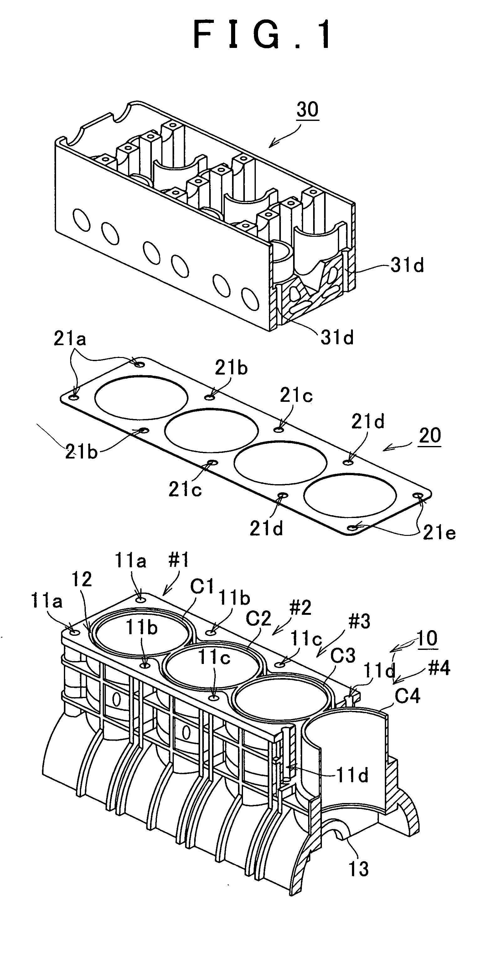
[0036]FIG. 1 shows an entire structure of a main portion of an internal combustion engine according to the embodiment. As shown in FIG. 1, the main portion of the internal combustion engine includes a cylinder block 10, a gasket 20, and a cylinder head 30.

[0037] The cylinder block 10 includes cylinders C1 to C4 which house pistons for cylinders #1 to #4, respectively. Between external surfaces of the cylinders C1 to C4 and an internal surface of the cylinder block 10, a water jacket 12 is formed. In the cylinder block 10, bearings 13 for a crank journal are formed at portions at both ends of a cylinder alignment and portions between the cylinders C1 and C2, cylinders C2 and C3, and cylinders C3 and C4. The...


PUM


Abstract

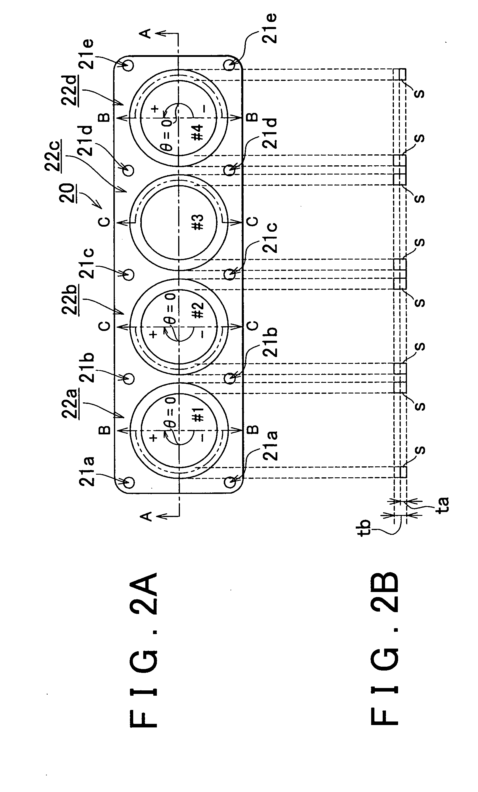
A gasket has seal portions at portions contacting peripheries of upper end portions of internal surfaces of cylinders, respectively. By being provided with a stopper, each of the seal portions is formed as a thick portion in the gasket. The stopper of each of the seal portions has a portion whose thickness is greater than a thickness of the stopper of each of the seal portions corresponding to cylinders at both ends of the cylinder alignment.

Description

INCORPORATION BY REFERENCE [0001] The disclosure of Japanese Patent Application No. 2003-303503 filed on Aug. 27, 2003 including the specification, drawings and abstract is incorporated herein by reference in its entirety. BACKGROUND OF THE INVENTION [0002] 1. Field of the Invention [0003] The invention relates to a seal structure for a multi-cylinder internal combustion engine, in which sealing is provided between a cylinder block and a cylinder head when the cylinder block and the cylinder head are fastened to each other with a bolt through a gasket. [0004] 2. Description of the Related Art [0005] In a seal structure for an internal combustion engine, generally, there is provided a gasket having a seal portion at a portion contacting a periphery of an upper end portion of an internal surface of each cylinder. An example of such a seal portion is disclosed in “cylinder head gasket structure” in Toyota Technical Report No. 12434 issued on Jul. 31, 2001. This technical report disclos...

Claims


Application Information

Patent Timeline
IPC IPC(8): F02F11/00F16J15/08F02F1/00
CPCF16J15/0818
Inventor YASUKI, AKIRATAKENAKA, KAZUNARI
Owner TOYOTA JIDOSHA KK
Learn More