EMI Shielding Textile Fabric, Wrappable Sleeve Constructed Therefrom and Method of Construction Thereof

a technology of textile fabric and shielding shielding, which is applied in the field of textile fabrics for providing protection against electromagnetic interference, can solve the problems of reducing the total conductivity provided by the yarns of the shielding shielding wall, and achieve the effect of enhancing the ability of the fabric to provide shielding protection against emi

Active Publication Date: 2014-09-18
FEDERAL MOGUL POWERTAIN LLC
View PDF3 Cites 92 Cited by
  • Summary
  • Abstract
  • Description
  • Claims
  • Application Information

AI Technical Summary

Benefits of technology

[0005]In accordance with one aspect of the invention, a textile fabric for routing and protecting an electrical member against electromagnetic interference is provided. The fabric forms an elongate wall constructed from lengthwise extending warp yarns woven with widthwise extending weft yarns. At least some of the warp yarns are electrically conductive and have a first diameter. T

Problems solved by technology

The holes ultimately result in the passage of high frequency EMI as well as potentially diminishing the total conductivity provided by yarns of the sleeve wall, which in tur

Method used


Image

  • EMI Shielding Textile Fabric, Wrappable Sleeve Constructed Therefrom and Method of Construction Thereof
  • EMI Shielding Textile Fabric, Wrappable Sleeve Constructed Therefrom and Method of Construction Thereof
  • EMI Shielding Textile Fabric, Wrappable Sleeve Constructed Therefrom and Method of Construction Thereof

Examples


Embodiment Construction

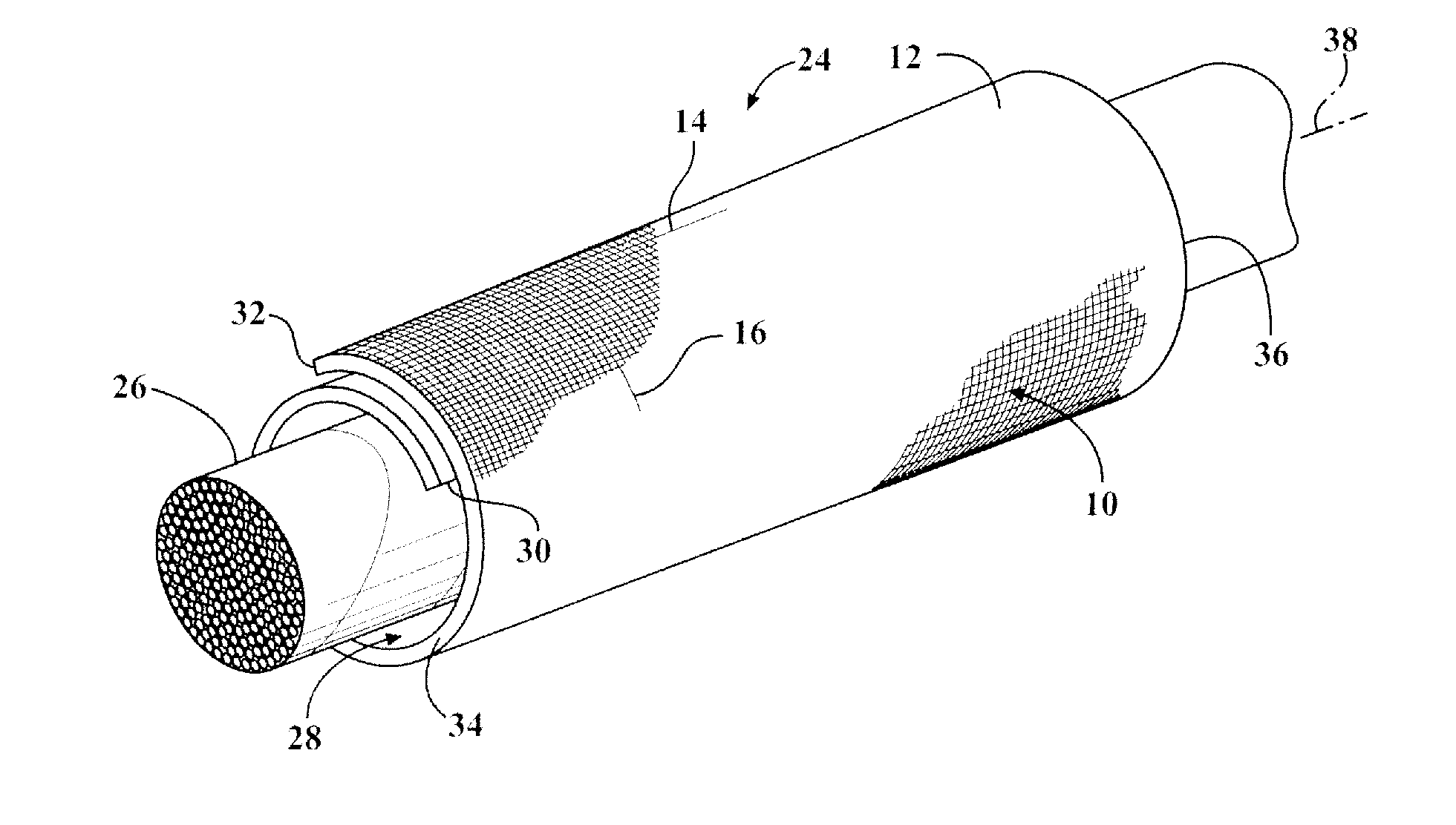
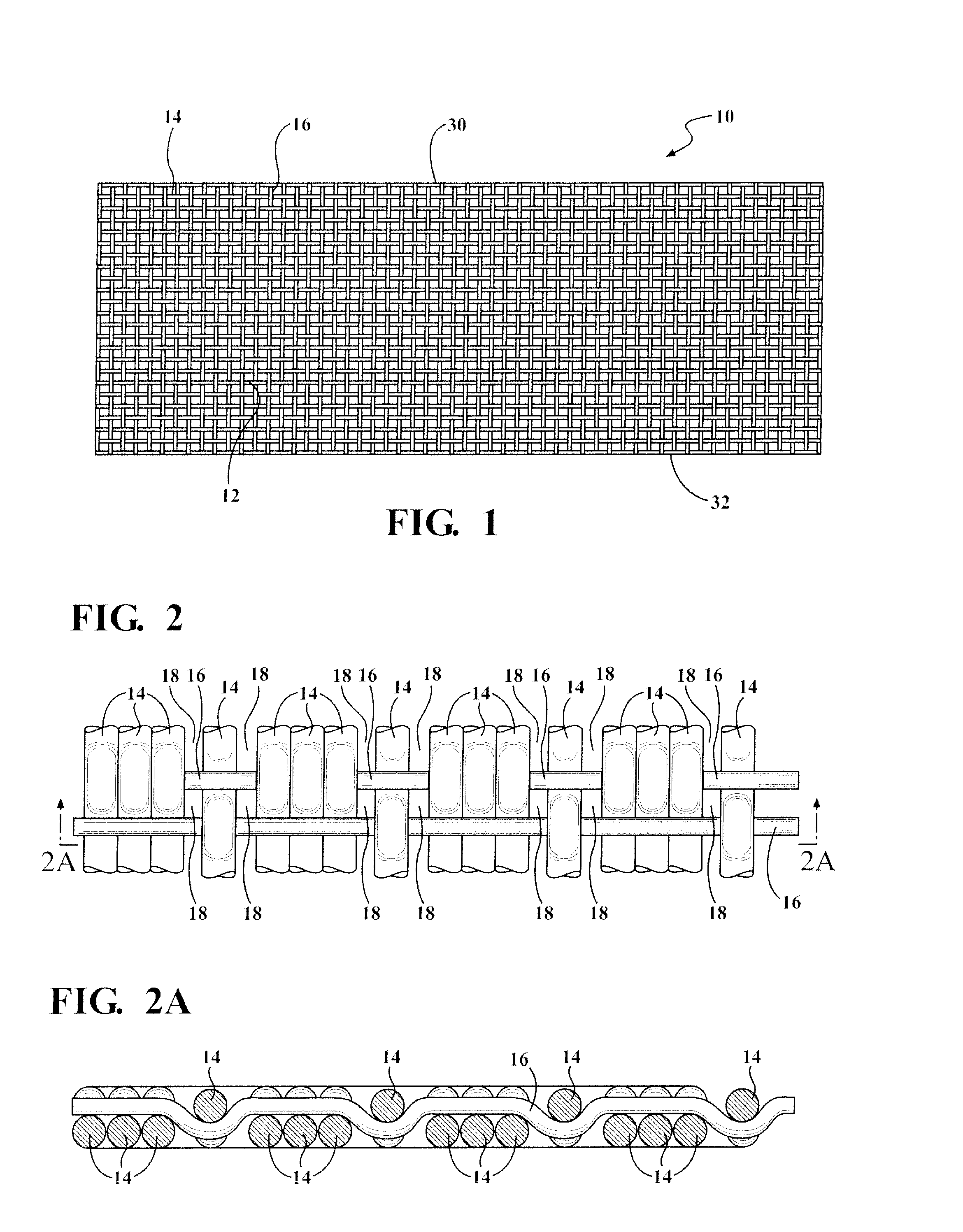
[0032]Referring in more detail to the drawings, FIG. 1 shows a plan view of textile fabric 10 constructed in accordance with one aspect of the invention. The fabric 10 is constructed as an elongate wall 12 from lengthwise extending warp yarns 14 woven with widthwise extending weft yarns 16. At least some, a plurality, or all of the warp yarns 14 are electrically conductive and have a first diameter and the weft yarns 16 have a second diameter, wherein the second diameter is at about, and preferably at least 25 percent less than the first diameter. As such, upon weaving the fabric 10, the conductive warp yarns 14 are brought into closer proximity with one another than if the weft yarns 16 were the same size as the warp yarns 14, thereby enhancing the ability of the fabric 10 to provide shielding protection against EMI.

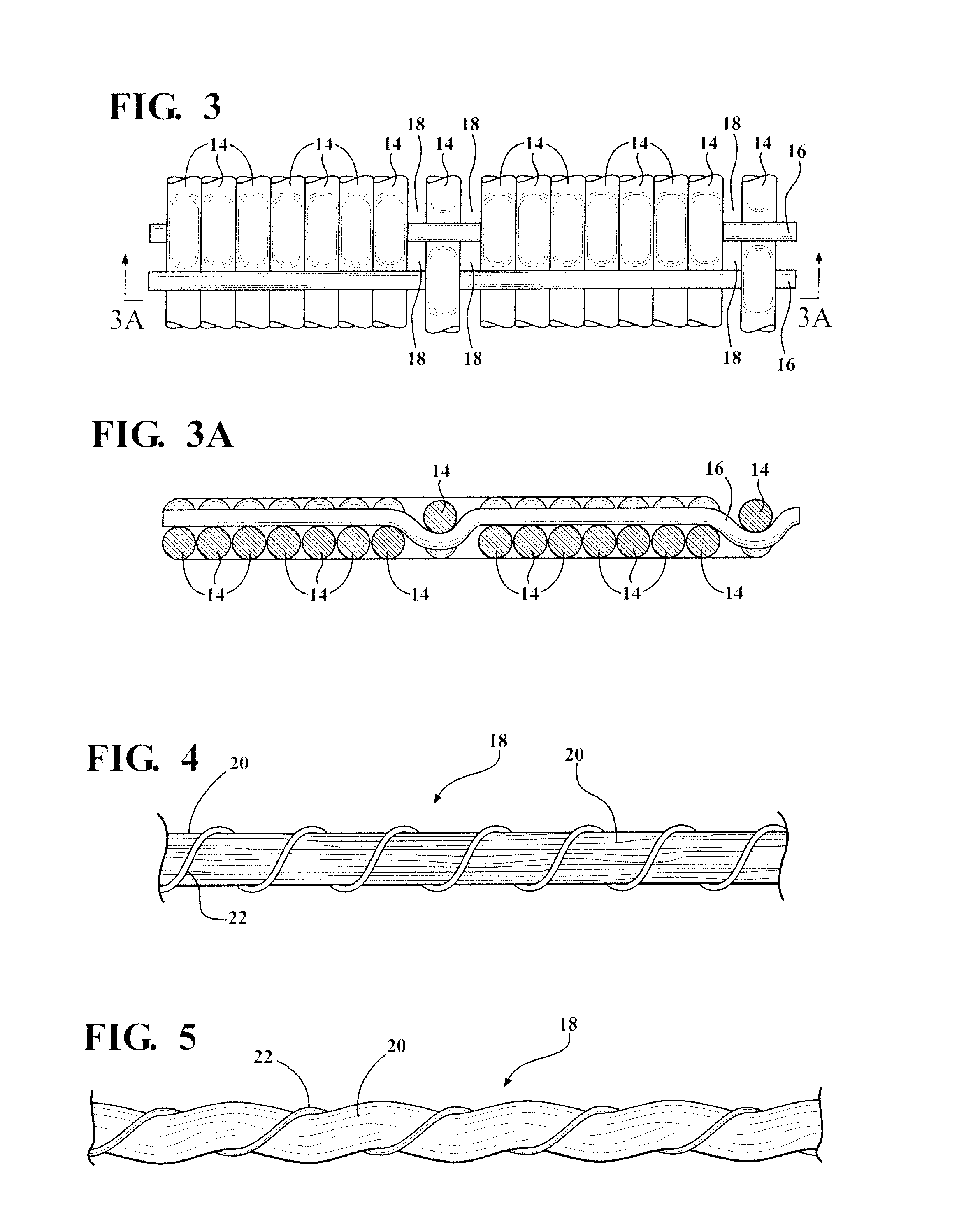
[0033]The fabric 10 can be woven in a plain weave pattern, however, this results in an increased number of openings 18 (with 2 opening being created at each intersectio...


PUM

PropertyMeasurementUnit
Fractionaaaaaaaaaa
Diameteraaaaaaaaaa
Electrical conductoraaaaaaaaaa

Abstract

A textile fabric, sleeve formed therefrom, and methods of construction thereof are provided. The fabric forms an elongate wall constructed from lengthwise extending warp yarns woven with widthwise extending weft yarns. At least some of the warp yarns are electrically conductive and have a first diameter. The weft yarns have a second diameter that is at least 25 percent less than the first diameter of the warp yarns. As such, the conductive warp yarns are brought into closer proximity with one another than if the weft yarns were the same diameter as the warp yarns. Accordingly, the ability of the fabric and sleeve formed therewith to provide shielding protection against EMI is enhanced.

Description

BACKGROUND OF THE INVENTION[0001]1. Technical Field[0002]This invention relates generally to textile fabrics for providing protection against electromagnetic interference, and more particularly to woven fabrics for protecting electrical members against electromagnetic interference.[0003]2. Related Art[0004]It is known to wrap electrical members, such as wires and wire harnesses, in textile protective sleeves, such as in automobiles, aircraft or aerospace craft, to provide protection to the wires against electromagnetic interference (EMI). In order to achieve the desired protection, considerations need to be given to the type of EMI protection desired, whether high frequency EMI, low frequency EMI, or both. In textile sleeves, such as woven sleeves, openings, also referred to as holes, are inherently formed in a wall of the sleeve between adjacent and overlapping yarns. The holes ultimately result in the passage of high frequency EMI as well as potentially diminishing the total condu...

Claims


Application Information

Patent Timeline
IPC IPC(8): H05K9/00D03D15/00D03D1/00D03D15/567
CPCH05K9/009D03D15/00D03D1/0088D02G3/441D03D1/0058D03D13/004D10B2101/20D03D15/43D03D15/567D03D15/47D03D1/0043
Inventor HARRIS, DAVID A.MALLOY, CASSIE M.WINTERS, DANNY
Owner FEDERAL MOGUL POWERTAIN LLC
Why Eureka
Try Eureka