Fire resistant acoustic panel

a technology of acoustic panels and fire-retardant materials, which is applied in the field of sound control, can solve the problems of a substantial environmental risk, system reduction or non-existent fire protection level installation, and system reduction or level reduction

Inactive Publication Date: 2014-09-18
JOHNSON LAHNIE
View PDF0 Cites 23 Cited by
  • Summary
  • Abstract
  • Description
  • Claims
  • Application Information

AI Technical Summary

Benefits of technology

[0048]In another embodiment of the invention the sound absorbing member is defined by a first and second face surface and a first, a second, a third, and a fourth peripheral edge. A sound blocking member is defined by a first and second face surface and a first, a second, a third, and a fourth peripheral edge peripheral edge. The first and second adjacent peripheral edges of the sound blocking material overhang the first and second adjacent peripheral edges of the sound absorbing material for providing an overlap of the sound blocking members between a first and a second adjacent acoustic panel, thereby providing a continuous uninterrupted array of sound blocking members.

Problems solved by technology

The development of sound absorbing and sound blocking systems has at times resulted in systems having a reduced fire protection level.
Installation of systems having reduced or non-existent fire protection levels comprises a substantial risk for the environment.

Method used


Image

  • Fire resistant acoustic panel
  • Fire resistant acoustic panel
  • Fire resistant acoustic panel

Examples


first embodiment

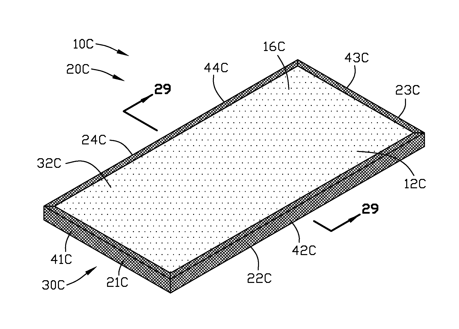
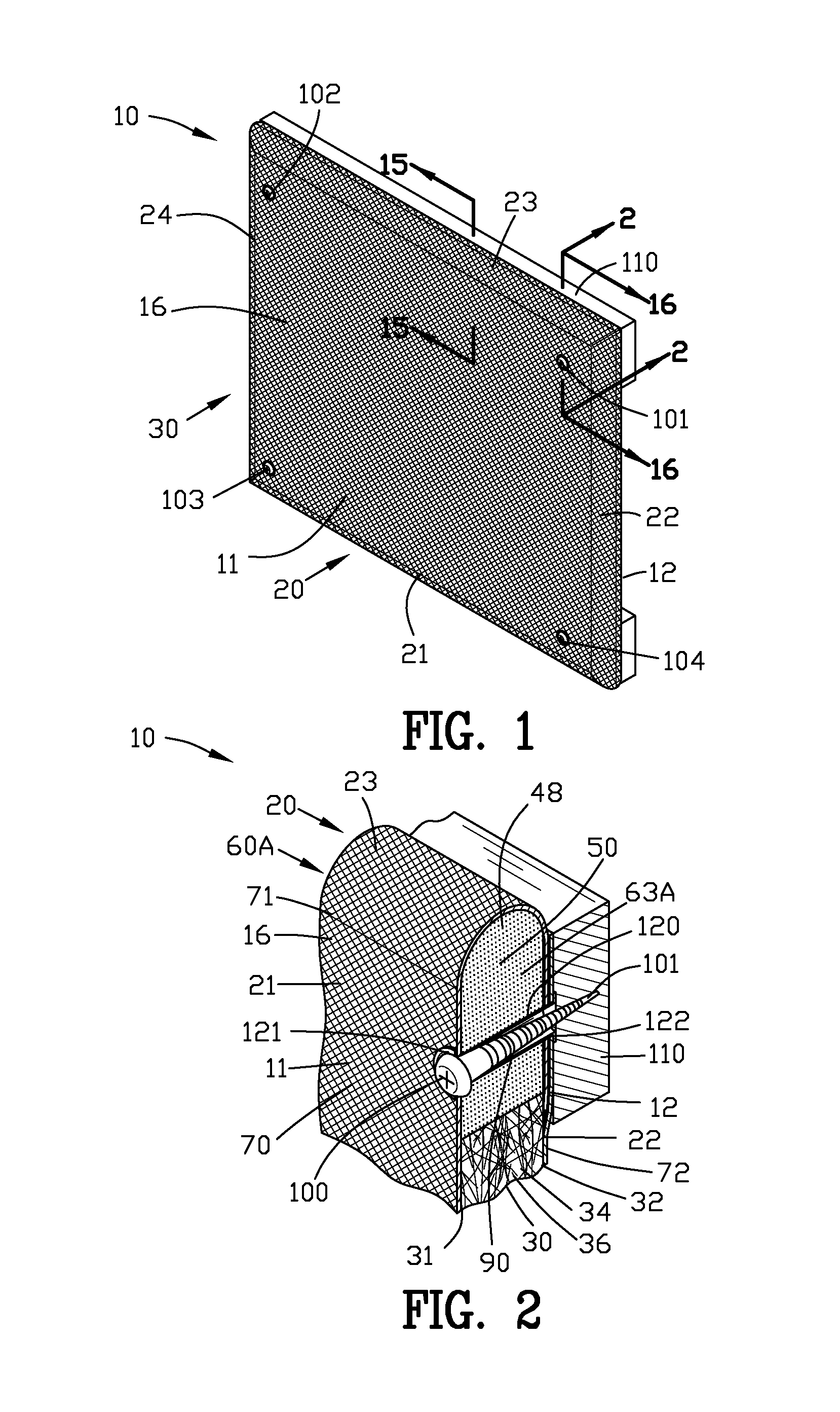
[0100]FIG. 1 is an isometric view of an improved, acoustic panel 10 of the present invention installed in an outdoor or a hazardous environment. The improved acoustic panel 10 comprises a first and a second face surface 11 and 12. Each of the first and second face surfaces 11 and 12 includes a multiplicity of pores 16 for receiving sound and / or noise from the environment.

[0101]The improved acoustic panel 10 comprises a plurality of peripheral edges 20 shown as peripheral edges 21-24. Although the improved acoustic panel 10 has been shown as having a rectangular configuration with four peripheral edges 21-24, it should be understood that the improved acoustic panel 10 may have configurations different than a rectangular configuration.

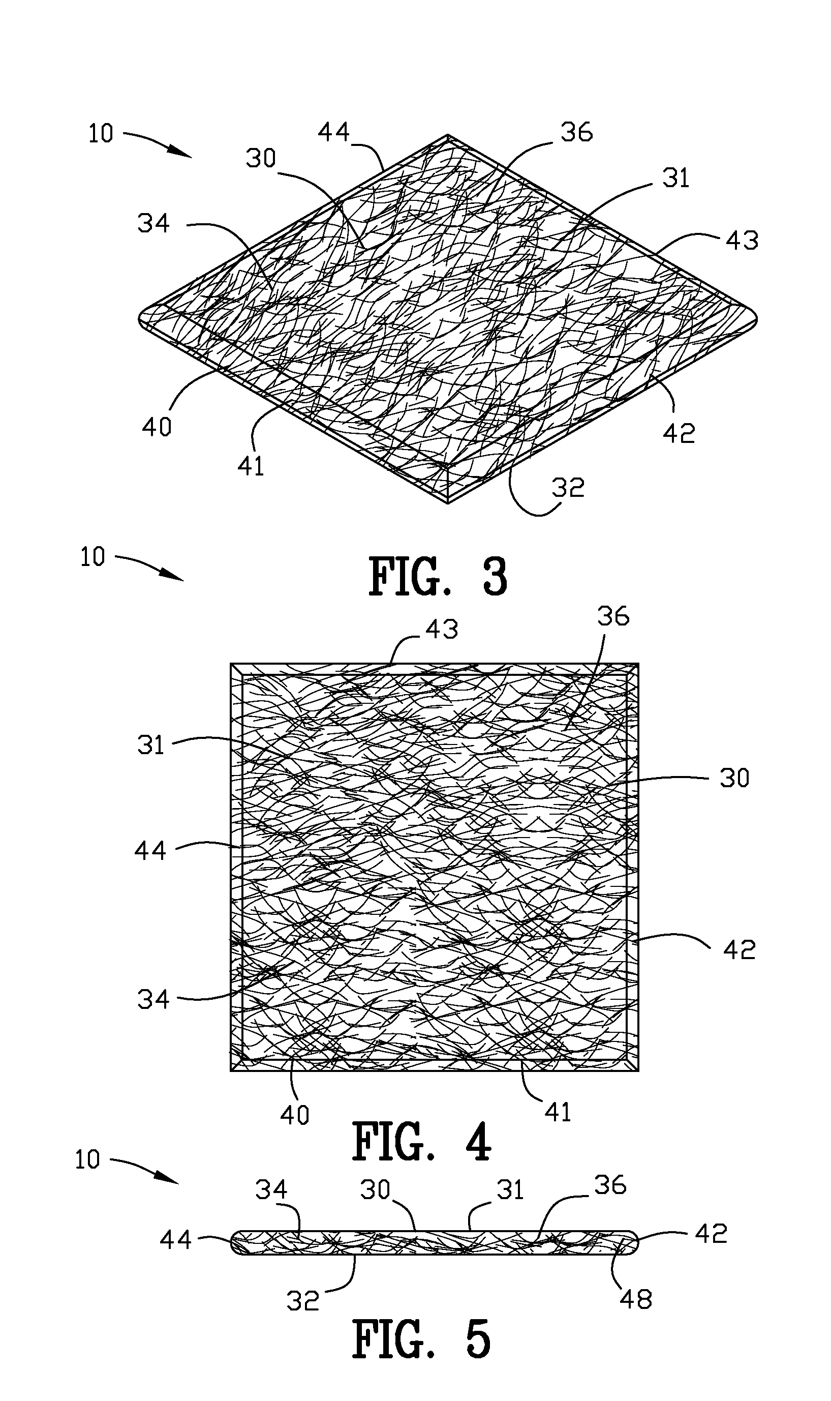
[0102]FIG. 2 is an enlarged isometric sectional view along line 2-2 in FIG. 1. The improved acoustic panel 10 comprises a water resistant sound absorbing member 30 which comprises a first and a second face surface 31 and 32. The improved acoustic panel 1...

second embodiment

[0123]In this second embodiment of the invention, the support frame 60 of the improved acoustic panel 10A includes an internal frame 60A and an external frame 60B. The internal frame 60A includes a water resistant curable polymeric material 50 impregnated into a portion of each of the plurality of peripheral edges 41-44 of the sound absorbing member 30. The internal frame 60A may be formed in a manner similar to the internal frame 60 shown in FIGS. 1-16.

[0124]The external frame 60B is located about the plurality of peripheral edges surfaces 41-44 of the sound absorbing member 30. The external frame 6013 includes a rigid material overlying a portion of each of the plurality of peripheral edges 41-44 of the sound absorbing member 30. The external frame 6013 overlies the plurality of peripheral edges 41-44 and overlies the internal frame 60A of the sound absorbing member.

[0125]The improved acoustic panel 10A includes a water resistant sound blocking member 130 for blocking the transmis...

third embodiment

[0130]FIGS. 21 and 22 are isometric views of an improved acoustic panel 10B of the present invention installed on a support 110B in an outdoor or a hazardous environment. In this example, the support 110B is shown as a chain link fence of conventional design. The mounting fasteners 100B are shown as wire, fiber or plastic fasteners for securing the improved acoustic panel 10B to the support 110B. Although the support 110B has been shown as a chain link fence of conventional design, it should be appreciated that numerous other ways and methods may be used for supporting and or hanging or otherwise spending the improved acoustic panel with them and environment.

[0131]FIGS. 23 and 24 are enlarged sectional views of the sound reducing panel 10B of FIG. 21 with the support 110B being removed for the purposes of clarity. In this third embodiment of the invention, the support frame 60 of the improved acoustic panel 10B includes an external frame 60B. The improved acoustic panel 10B has no i...


PUM


Abstract

An apparatus is disclosed for an improved acoustic panel comprising a sound absorbing member defined by a first and second face surface and a peripheral edge for absorbing sound from a sound source. A sound blocking member is defined by a first and second face surface and a peripheral edge for blocking the transmission of sound through the sound reducing panel. A first fire retardant spacing material is interposed between and affixed to the second face surface of the sound absorbing material and the first face surface of the sound blocking material. A second fire retardant spacing material having a first and a second face surface and a peripheral edge with the first face surface of the second spacing material is affixed to the second face surface of the sound blocking material. A fire retardant coating is affixed to the second face surface of the second spacing material.

Description

BACKGROUND OF THE INVENTION[0001]1. Field of the Invention[0002]This invention relates to sound control and more particularly to an improved fire retardant acoustical panel suitable for indoor use such as a ceiling tile and the like.[0003]2. Background of the Invention[0004]The prior art has known various types of devices and methods for reducing the level of sound within an environment. The various types of devices and methods of the prior art for reducing the level of sound within an environment included a diverse and variety of apparatuses and methods adapted for many as specific applications and uses.[0005]One particular type of device for reducing the level of sound within an environment comprises the use of sound reducing panels and / or sound absorbing devices. Various types of sound reducing panels and sound absorbing devices have been incorporated by the prior art to reduce the level of sound and / or to selectively reduce or inhibit reflection of sound from reflective surfaces...

Claims


Application Information

Patent Timeline
Patent Type & Authority Applications(United States)
IPC IPC(8): G10K11/16
CPCG10K11/168E04B2/7403E04B1/86E04B2001/8433E04B2001/8263E04B2001/8452E04H3/22E01F8/0017E01F8/0029
Inventor JOHNSON, LAHNIE
Owner JOHNSON LAHNIE
Why Eureka
Try Eureka