Permanent magnet electrical machines and methods of assembling the same

a permanent magnet and electrical machine technology, applied in the direction of magnetic circuit rotating parts, magnetic circuit shape/form/construction, stator/rotor body manufacturing, etc., can solve the problems of less torque production, less efficient machine, and reduced machine efficiency

Active Publication Date: 2014-09-18
REGAL BELOIT AUSTRALIA PTY LTD
View PDF25 Cites 23 Cited by
  • Summary
  • Abstract
  • Description
  • Claims
  • Application Information

AI Technical Summary

Problems solved by technology

These eddy currents generate resistive losses resulting in less torque production, and therefore a less efficient machine.
Excessive heat produced by the eddy currents also reduces the machine's efficiency and may lead to the failure of an adhesive used to retain the permanent magnets on the spinning rotor.
The loss of magnet retention causes significant damages to the machine and may lead to machine failure.
More specifically, rotor magnets passing through the open area between stator teeth, coupled with the attraction to and repulsion from the solid teeth of the stator, cause vibrations, cogging torque, and potentially motor noise, any amount of which may be objectionable to a user.
Audible machine noise is unacceptable in many applications.
In such applications these torque pulses and the effects of cogging may result in operational deficiencies and / or acoustical noise that can be objectionable to an end user of the machine.
However, semi-closed stator slots typically increase the complexity and expense of coil winding machinery.
Stators that incorporate semi-closed slots with tooth extensions are more difficult to fabricate, and the area available for the copper wire windings that can be inserted or wound into such slots is limited.

Method used


Image

  • Permanent magnet electrical machines and methods of assembling the same
  • Permanent magnet electrical machines and methods of assembling the same
  • Permanent magnet electrical machines and methods of assembling the same

Examples


Embodiment Construction

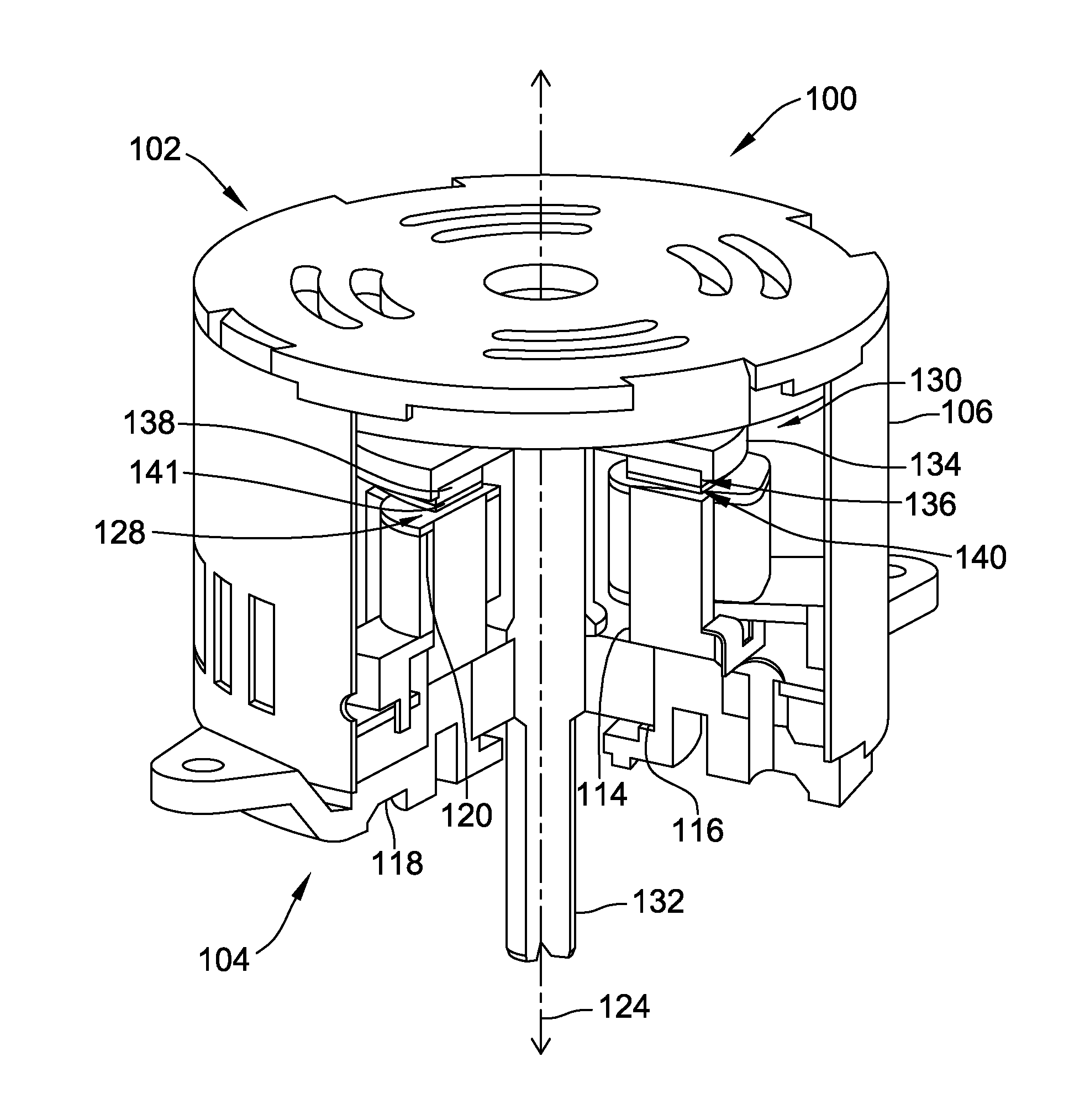
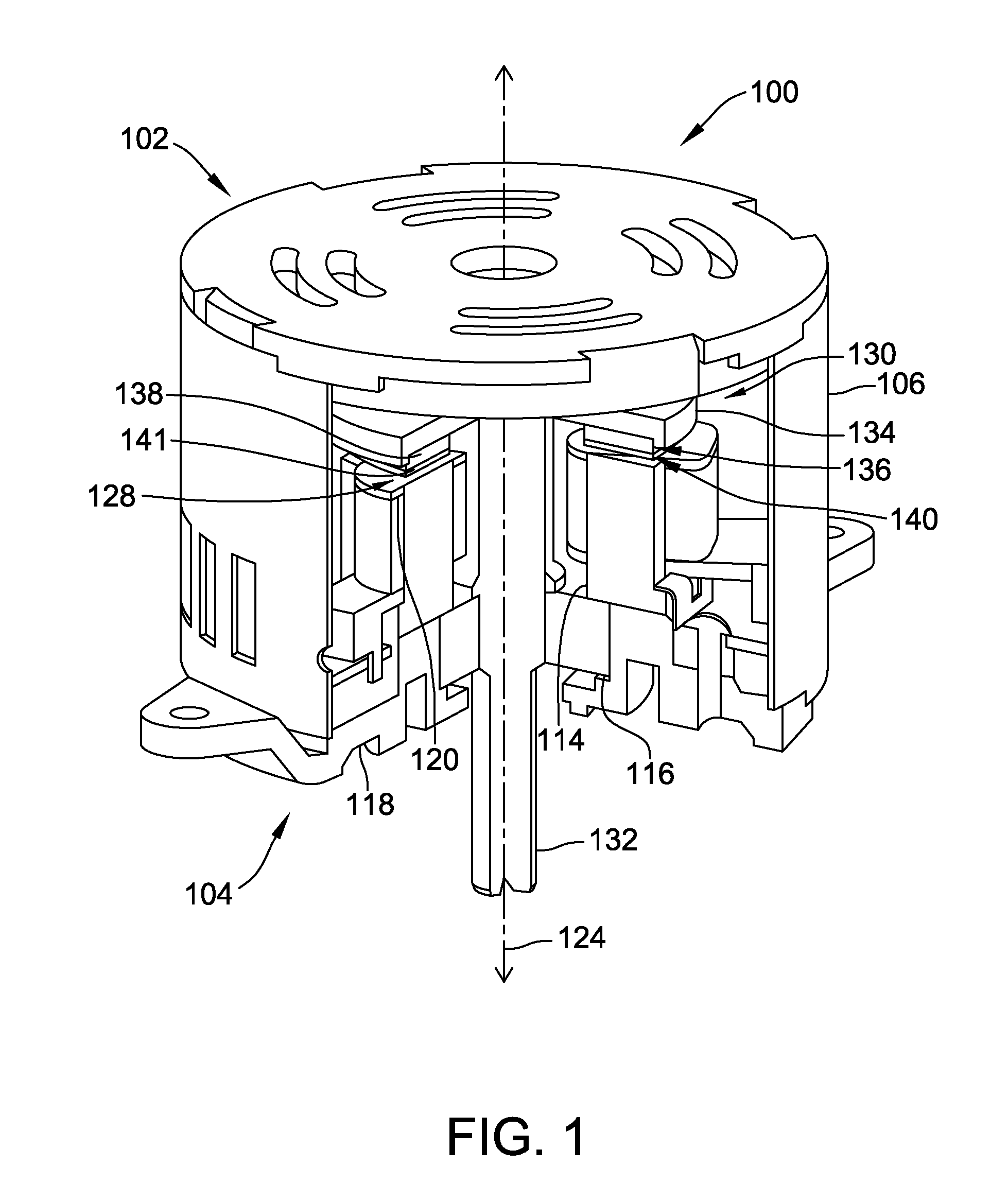
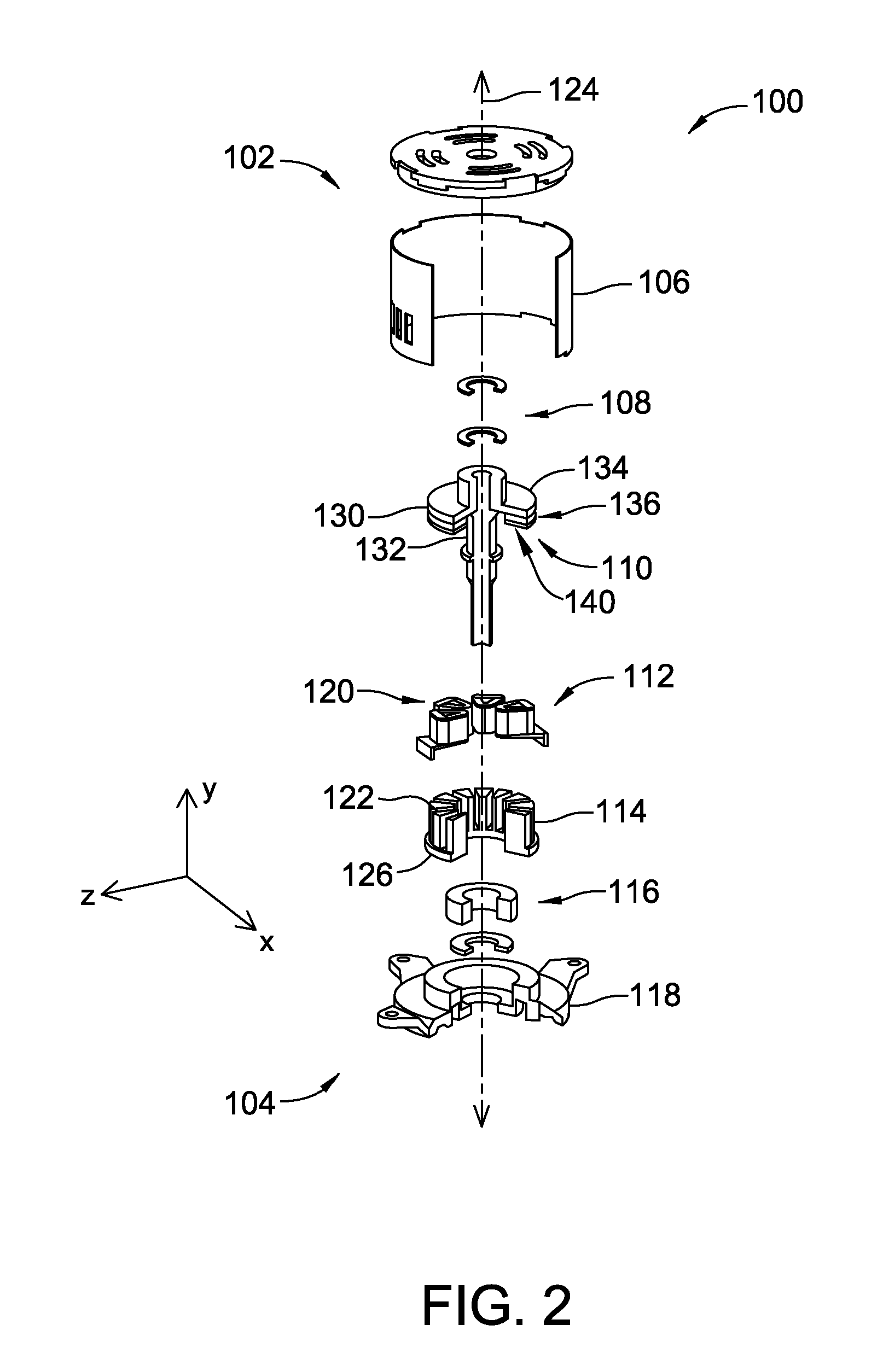
[0015]FIG. 1 is a partial cut-away view of an exemplary embodiment of an axial flux electric machine 100. FIG. 2 is an exploded, partially cut-away, view of axial flux electric machine 100. Although machine 100 is described herein as an axial flux machine, machine 100 may alternatively be a radial flux machine. In the exemplary embodiment, electric machine 100 is an electric motor. Alternatively, electric machine 100 may operate as either a motor or a generator. Components common to FIGS. 1 and 2 are identified with the same reference numerals. Components are described herein as including a top surface 102 generally facing what is referred to herein as a top of machine 100, and a bottom surface 104 generally facing what is referred to herein as a bottom of machine 100.

[0016]In the exemplary embodiment, electric machine 100 is coupled to a work component (not shown) included within a commercial and / or industrial application. The work component may include, but is not limited to, a pu...


PUM

PropertyMeasurementUnit
frequenciesaaaaaaaaaa
thicknessaaaaaaaaaa
magnetic fluxaaaaaaaaaa

Abstract

An electric machine comprising a permanent magnet rotor assembly is provided. The electric machine comprises a permanent magnet rotor assembly comprising a plurality of permanent magnets coupled to a rotor disk and a plurality of magnet shims coupled to the plurality of permanent magnets opposite the rotor disk. Each magnet shim of the plurality of magnet shims has a substantially complementary shape as a respective permanent magnet of the plurality of permanent magnets. The electric machine further comprises a stator core comprising a plurality of stator teeth that define a plurality of slots therebetween. At least one of the plurality of magnet shims is configured to direct magnetic flux from at least one of the plurality of permanent magnets to at least one stator tooth of the plurality of stator teeth.

Description

BACKGROUND[0001]The embodiments described herein relate generally to permanent magnet electrical machines, and more particularly, to methods and systems for steering magnetic flux using a permanent magnet rotor.[0002]Permanent magnet electrical machines are used in a wide variety of systems operating in a wide variety of industries, such as in pump systems or air handling units. As such, permanent magnet electrical machines are subject to many operating conditions. In such a machine, the torque resulting from the magnetic interaction between the rotor and stator may be reduced by eddy currents generated by magnetic flux flowing through the magnets. Eddy currents are created when a magnet experiences a change in the intensity or direction of the magnetic flux at any point within the magnet. These eddy currents generate resistive losses resulting in less torque production, and therefore a less efficient machine. Furthermore, eddy currents may transform some forms of energy, such as ki...

Claims


Application Information

Patent Timeline
Patent Type & Authority Applications(United States)
IPC IPC(8): H02K1/27H02K15/03
CPCH02K15/03H02K1/2793Y10T29/49009H02K1/2795H02K1/2753H02K21/24
Inventor PATTERSON, DEAN JAMESROHOZA, RAFAL PAWELCAMILLERI, STEVEN PETERTURNER, MATTHEWLANGFORD, CHARLES RICHARD
Owner REGAL BELOIT AUSTRALIA PTY LTD
Why Eureka
Try Eureka