Half- Or Quarter-Cycle Current Regulator For Non-Isolated, Line Voltage L.E.D. Ballast Circuits

a technology of l.e.d. or ballast circuit and current regulator, which is applied in the direction of electroluminescent light sources, semiconductor lamp usage, electroluminescent lamp sources, etc., can solve the problems of noise in the visible frequency range, circuit is subject to any noise that might be present, and detrimental to the performance of leds

Active Publication Date: 2014-09-18
4382412 CANADA INC
View PDF2 Cites 6 Cited by
  • Summary
  • Abstract
  • Description
  • Claims
  • Application Information

AI Technical Summary

Benefits of technology

[0014]In still another implementation, the present disclosure is directed to a circuit. The circuit includes a rectifier, a load, an electrically variable resistor comprising at least one pin, a sensor, at least two integrators, and at least one switch, wherein the rectifier, the load, the electrically variable resistor, and the sensor are arranged in series; the at least one switch selects at least one of the at least two integrators, electrically connecting a selected integrator with the at least one pin of the electrically variable resistor; and the electrically variable resistor moderates a circuit condition of the load.

Problems solved by technology

However, without electrolytic capacitors to filter (or “buffer”) the line voltage, the circuit is subject to any noise that might be present on the incoming power lines (or “mains”).
Particularly, noise in the visible frequency range, which extends up to about 100 Hz, may be detrimental to the performance of LEDs.
There are several ways that ideal line conditions may be disturbed such that alternating cycles and rising or falling edges may become asymmetrical from their counterparts.
These conditions may conspire to create an undesirable visible flicker in the LED light output.
For example, if an LED load draws current from an AC power source that is also connected to a circuit having a poor power factor, the rising and falling edges of the line voltage may become mismatched or asymmetrical.
Other sources of line distortion, such as fluorescent lighting ballasts, can easily cause mismatches between edges within the same cycle.
These devices often exhibit asymmetrical behavior in the different operating quadrants of the TRIAC which may result in each alternative half-cycle on the line having slightly differing durations.
When a wall dimmer using phase-cut style dimming is connected to the same AC power source as an LED driver, this difference in half-cycles may manifest itself in the LED light output as a disturbing flicker.
This works to an extent, but the time constant necessary for good regulation is longer than several cycles of the line voltage; therefore, this type of implementation cannot compensate for short-term fluctuations such as half-cycle or quarter-cycle asymmetry.
However, due to their large size and cost, utilizing an electrolytic capacitor in such a way can be detrimental to the compactness and / or price, and thus marketability, of a LED driver.

Method used


Image

  • Half- Or Quarter-Cycle Current Regulator For Non-Isolated, Line Voltage L.E.D. Ballast Circuits
  • Half- Or Quarter-Cycle Current Regulator For Non-Isolated, Line Voltage L.E.D. Ballast Circuits
  • Half- Or Quarter-Cycle Current Regulator For Non-Isolated, Line Voltage L.E.D. Ballast Circuits

Examples


Embodiment Construction

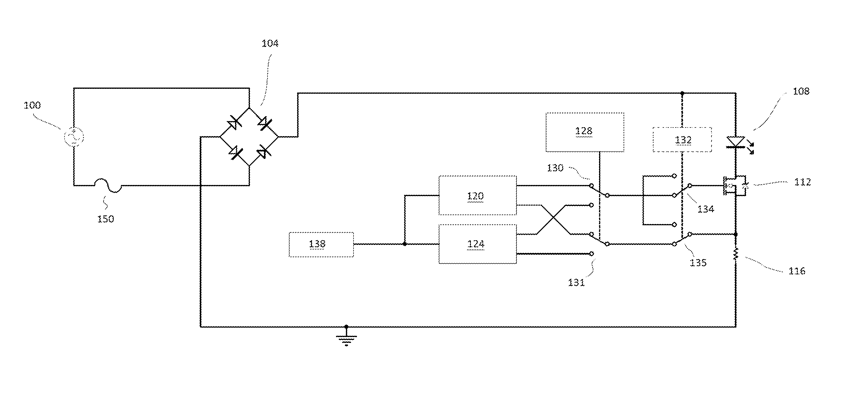
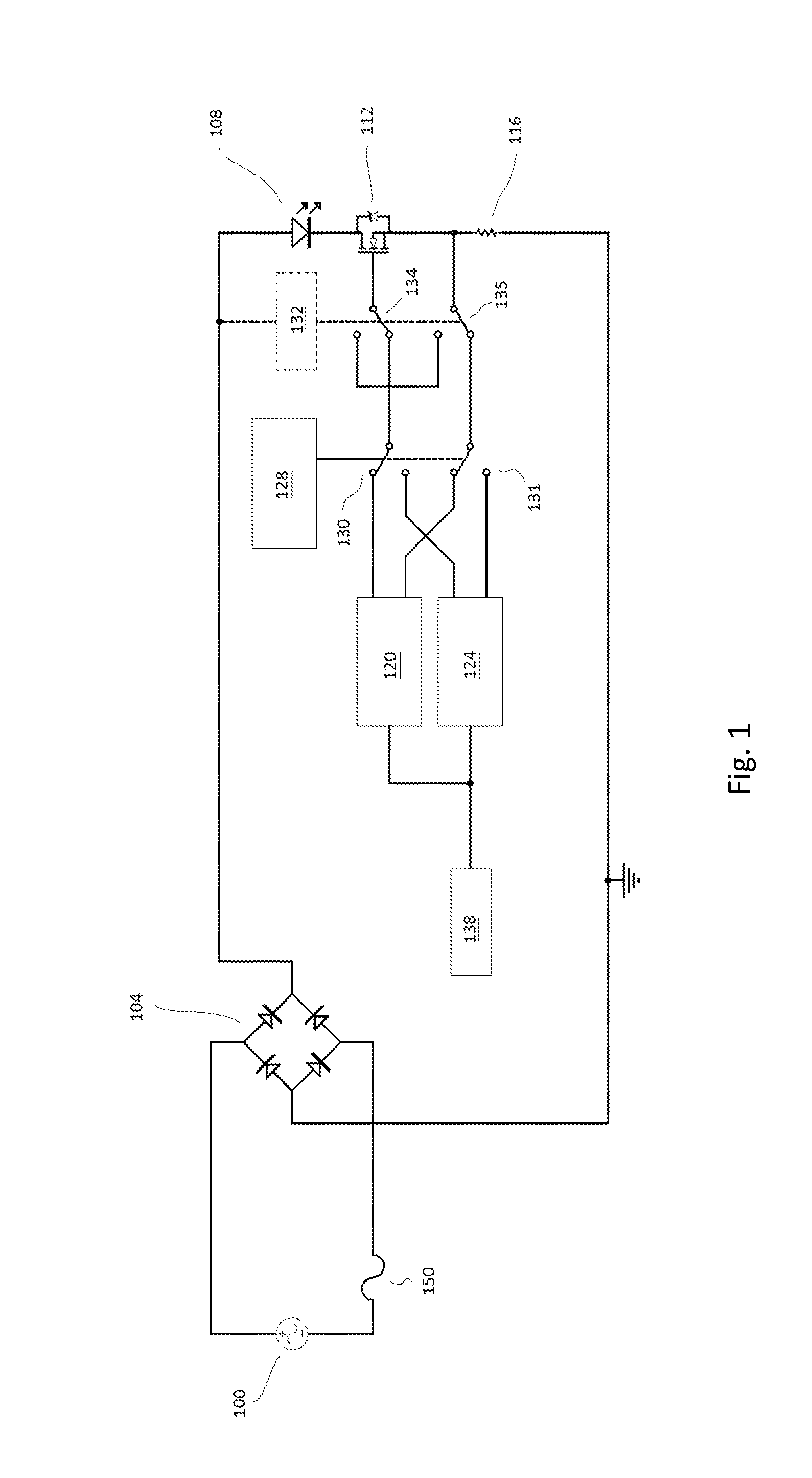
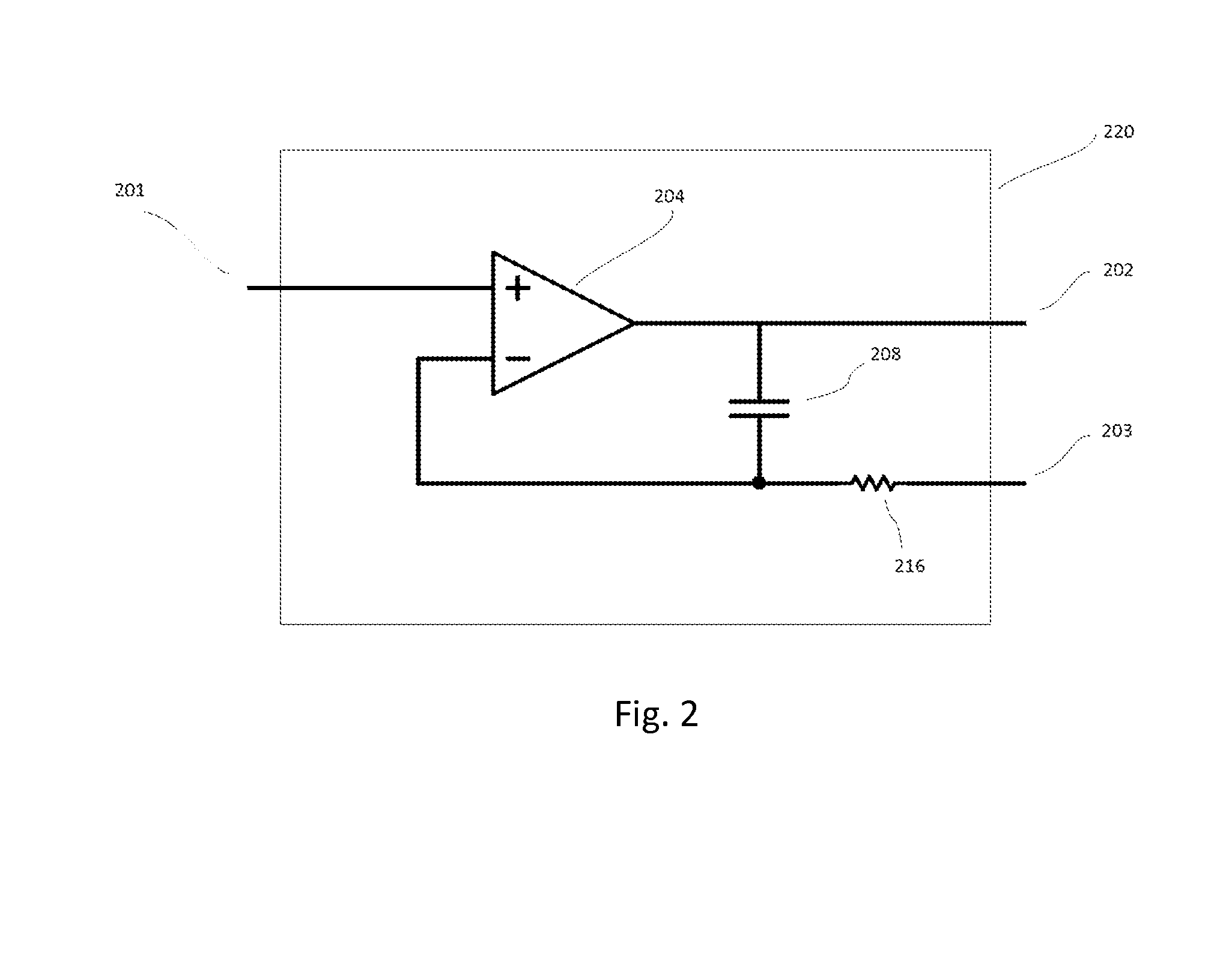
[0022]Embodiments of the present invention overcome disadvantages of using a large electrolytic capacitor as discussed above by providing a current regulator configured to adapt to line voltage variations by switching between separate integrators corresponding to the different parts of the incoming line voltage wave. In various embodiments, the integrators may be switched on and off in sequence using edge and / or zero-crossing detection methods, analog switches, and a one- or two-bit counter (or timer), or by any other suitable methods known in the art. In other embodiments, the integrators may be implemented with multi-layer ceramic capacitors (MLCC) or any other capacitors known in the art. However, it should be noted that no electrolytic capacitors are required and that the teachings of the present invention may be implemented in most instances with capacitors having a voltage rating not greater than about 10 V, and in other embodiments employing capacitors with a maximum voltage ...


PUM


Abstract

A current regulator for non-isolated, line voltage LED Driver circuits solves the problem of LED flicker caused by line noise in the visible frequency range. In one aspect of the invention, LED flicker frequency may be increased beyond the line frequency. In another aspect, line voltages in excess of LED voltage ratings may be tolerated. The driver may be implemented using discrete circuit elements or in software and utilizes separate current regulation for different segments of an AC line voltage cycle.

Description

FIELD OF THE INVENTION[0001]The present invention generally relates to the field of light-emitting diode (L.E.D. or LED) driver circuits. In particular, the present invention is directed to a half- or quarter-cycle current regulator for non-isolated, line voltage L.E.D. driver (“ballast”) circuits.BACKGROUND[0002]LEDs are solid-state devices that produce light when electrical current flows therethrough. They are typically polarized, low-voltage devices, although they may be combined into arrays requiring higher voltages. Despite having minimum and operating voltage specifications, LEDs are typically specified and regulated with respect to the amount of current required for operation. Unlike conventional loads that require a fixed voltage, LEDs typically require a near-constant current for ideal operation.[0003]An LED light source that runs directly from a commercial alternating current (AC) 120 volt (V) power supply (“line voltage”) usually requires a current-regulated ballast circu...

Claims


Application Information

Patent Timeline
Patent Type & Authority Applications(United States)
IPC IPC(8): H05B37/02H05B44/00
CPCH05B37/02H05B33/0812Y02B20/345H05B45/395Y02B20/30H05B45/56
Inventor LEWIS, JASON P.
Owner 4382412 CANADA INC
Why Eureka
Try Eureka