Multi-mode signal source

a signal source and multi-mode technology, applied in the direction of antenna details, antenna equipment with additional functions, antennas, etc., can solve the problems of affecting the performance of the structure, the inability to easily co-locate or angularly co-align, and the inability to easily co-locate sources

Active Publication Date: 2014-09-18
RAYTHEON CO
View PDF6 Cites 23 Cited by
  • Summary
  • Abstract
  • Description
  • Claims
  • Application Information

AI Technical Summary

Benefits of technology

[0002]Aspects and embodiments of the disclosure are directed to methods and apparatus for providing a multimode signal source that radiates multiple signals from a first location with substantially a common phase center. In particular, as discussed i

Problems solved by technology

Typically these sources can not be easily co-located or angularly co-aligned.
However, such structure suffers from

Method used


Image

  • Multi-mode signal source
  • Multi-mode signal source
  • Multi-mode signal source

Examples


Embodiment Construction

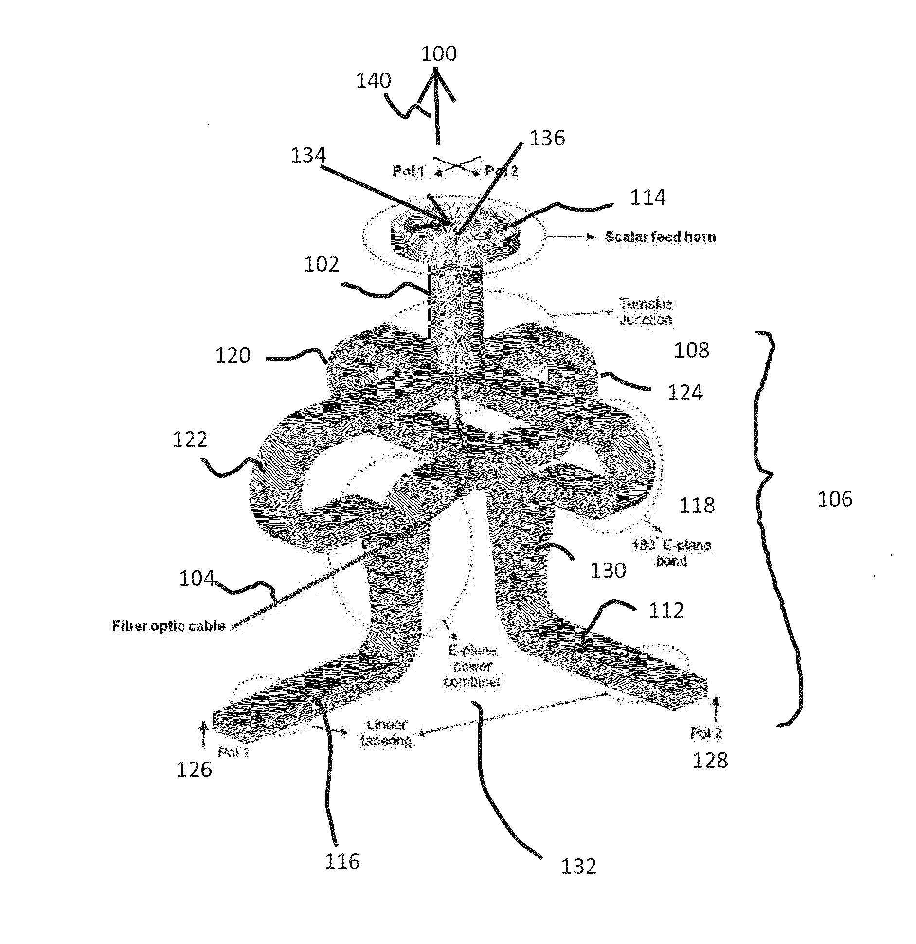
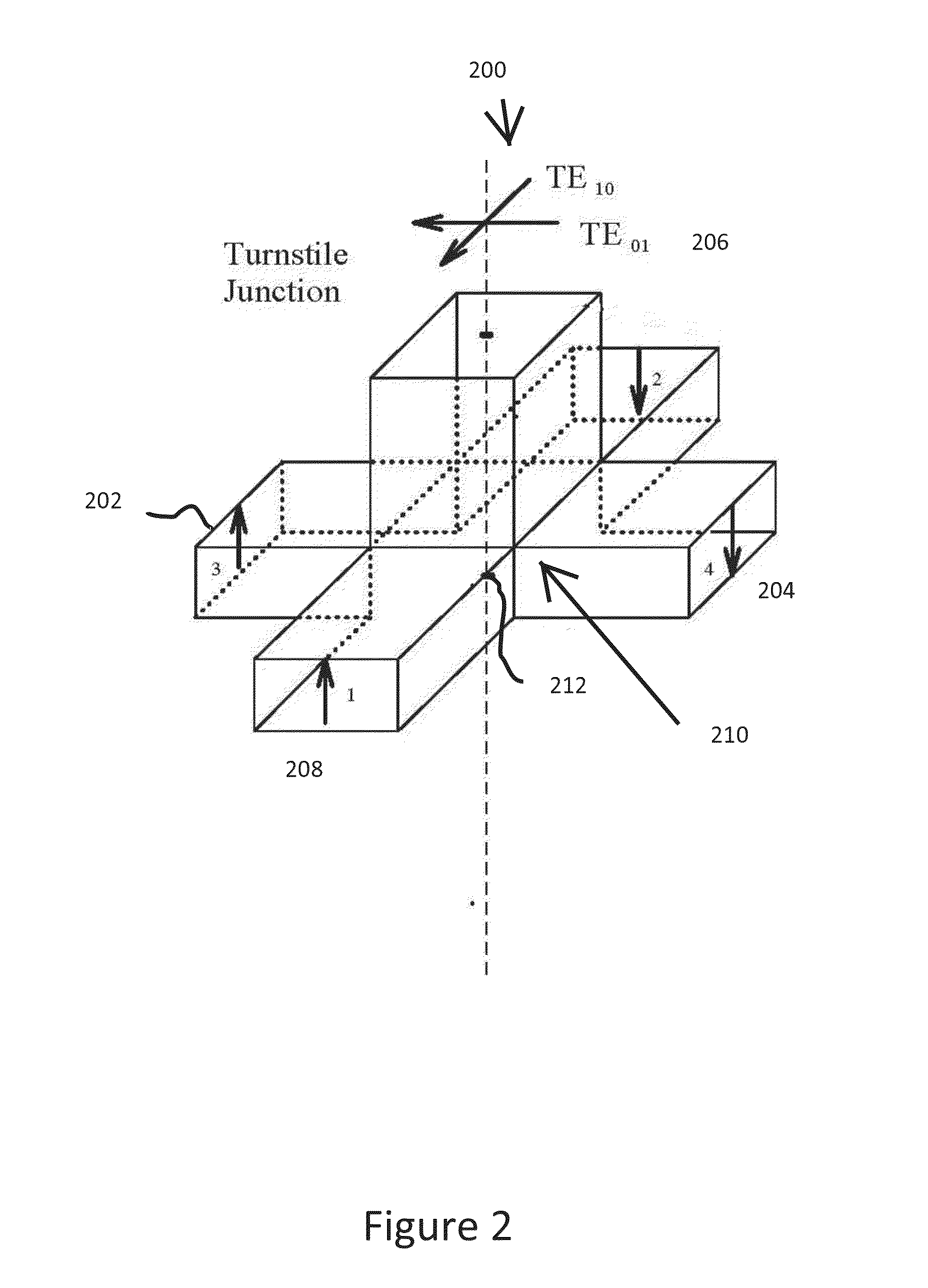
[0026]As is known in the art, a multimode radiation source may include a number of spatially distributed discrete signal sources that provide multiple wavelength signals. However, such sources don't provide multiple sources radiating multiple signals from a first location with substantially a common phase center. Accordingly, aspects and embodiments of this disclosure are directed to a providing a multimode signal source that radiates multiple signals from a first location with substantially a common phase center. In particular, aspects and embodiments disclosed herein provide for at least two signal sources to be co-located, co-aligned so that the at least two signals are radiated in a same direction, and that provide at least two signals that are radiated with substantially a common phase center.

[0027]It is to be appreciated that embodiments of the methods and apparatuses discussed herein are not limited in application to the details of construction and the arrangement of componen...


PUM


Abstract

A multimode radiation source is disclosed. One embodiment includes a waveguide radiator and an orthomode transducer coupled to the waveguide radiator to provide a first signal to the waveguide radiator. The waveguide radiator is configured to receive the first signal and to radiate the first signal at a first location as a first spherical wave signal with a first phase center. The multimode source also includes transmission medium coupled to the waveguide radiator and configured to radiate a second signal and a third signal from the first location as a second spherical wave and a third spherical wave with substantially the first phase center.

Description

BACKGROUND[0001]Current test systems for units under test (UUT) such as multi-mode seekers that operate at multiple wavelengths include a number of spatially distributed discrete signal sources that provide multiple wavelength signals and are subject to mis-alignment in position and angle. Typically these sources can not be easily co-located or angularly co-aligned. Alternatively, discrete tests can be performed at different test stations configured to operate at different wavelengths. However, such test facilities require either or both of significant metrology that allows the transfer of the optical axis of the measurement chamber of one sensor to each of the chambers of the other sensors, or significant floor space so as to move the sources far a-field from the multimode seeker UUT. Another known structure is disclosed in U.S. Pat. No. 5,012,250, which discloses an infrared (IR) radiator disposed in a center of an RF horn radiator to provide an IR and a radiofrequency (RF) source...

Claims


Application Information

Patent Timeline
IPC IPC(8): H01Q1/44
CPCH01Q1/44H01P1/161H01Q13/0208H01Q13/06H01Q13/065H01Q5/22
Inventor COOK, DAVID C.MCCARTHY, PATRICK L.CRAWFORD, JOHN OKERSONFAULKNER, DAVID A.MARTIN, DYLAN WILLIAM ROHYANSTRAIL, NICHOLAS D.
Owner RAYTHEON CO
Why Eureka
Try Eureka