Aircraft flight deck displays and systems and methods for enhanced display of obstacles in a combined vision display

a combined vision and display technology, applied in static indicating devices, instruments, navigation instruments, etc., can solve the problems of low resolution of the evs system, insufficient detection of certain obstacles, and particularly insidious obstacles, etc., to increase the potential for obstacle detection and avoidance, enhance the display of obstacles, and increase the awareness of obstacles

Active Publication Date: 2014-09-18
HONEYWELL INT INC
View PDF22 Cites 27 Cited by
  • Summary
  • Abstract
  • Description
  • Claims
  • Application Information

AI Technical Summary

Benefits of technology

[0045]It is to be appreciated that systems and methods for enhanced display of obstacles in a combined vision display have been provided. The vehicle operator gains heightened obstacle awareness by selectively bringing the obstacles (more specifically, the synthetic vision images of one or more obstacles) to the front of the combined vision display (by overlaying the synthetic vision images of the one or more obstacles over the EVS images) and selectively visually highlighting the synthetic vision images of the one or more obstacles, thereby increasing the potential of obstacle detection and avoidance regardless of obstacle size, and other conditions.

Problems solved by technology

However, the EVS system has low resolution and may not be sensitive enough to detect certain obstacles because of their size or other conditions.
For example, thin radio towers, high voltage wires, cables, power lines, etc. represent a particularly insidious obstacle hazard, as they are difficult to detect by the EVS system even during daylight with good visibility conditions.
Unfortunately, obstacle images in combined vision displays, even if within sensor detection range or in the database, may not be easily visible, thereby limiting obstacle awareness and decreasing the potential for obstacle avoidance.

Method used


Image

  • Aircraft flight deck displays and systems and methods for enhanced display of obstacles in a combined vision display
  • Aircraft flight deck displays and systems and methods for enhanced display of obstacles in a combined vision display
  • Aircraft flight deck displays and systems and methods for enhanced display of obstacles in a combined vision display

Examples


Embodiment Construction

[0015]The following detailed description is merely exemplary in nature and is not intended to limit the invention or the application and uses of the invention. As used herein, the word “exemplary” means “serving as an example, instance, or illustration.” Thus, any embodiment described herein as “exemplary” is not necessarily to be construed as preferred or advantageous over other embodiments. All of the embodiments described herein are exemplary embodiments provided to enable persons skilled in the art to make or use the invention and not to limit the scope of the invention which is defined by the claims. Furthermore, there is no intention to be bound by any expressed or implied theory presented in the preceding technical field, background, brief summary, or the following detailed description.

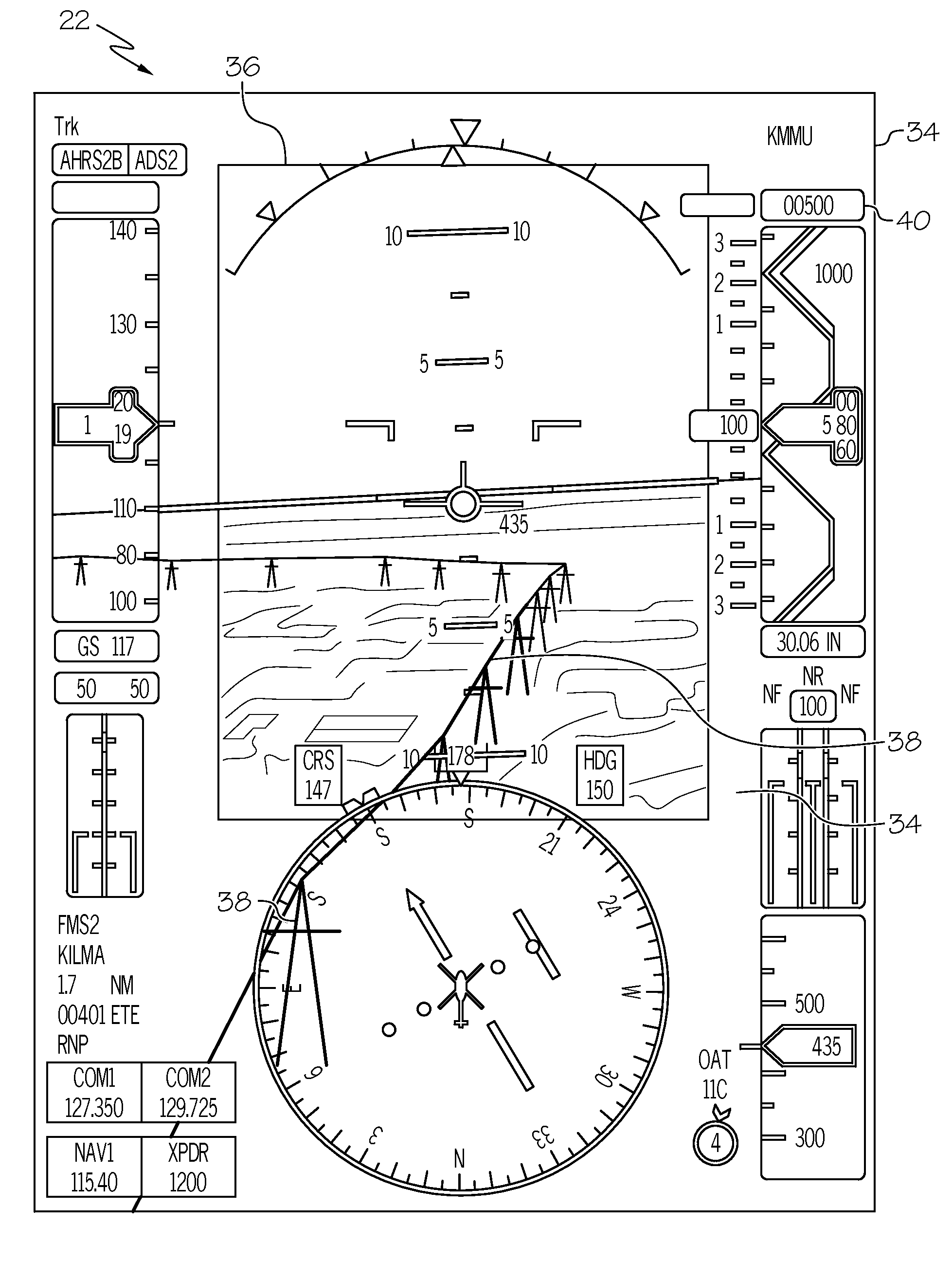
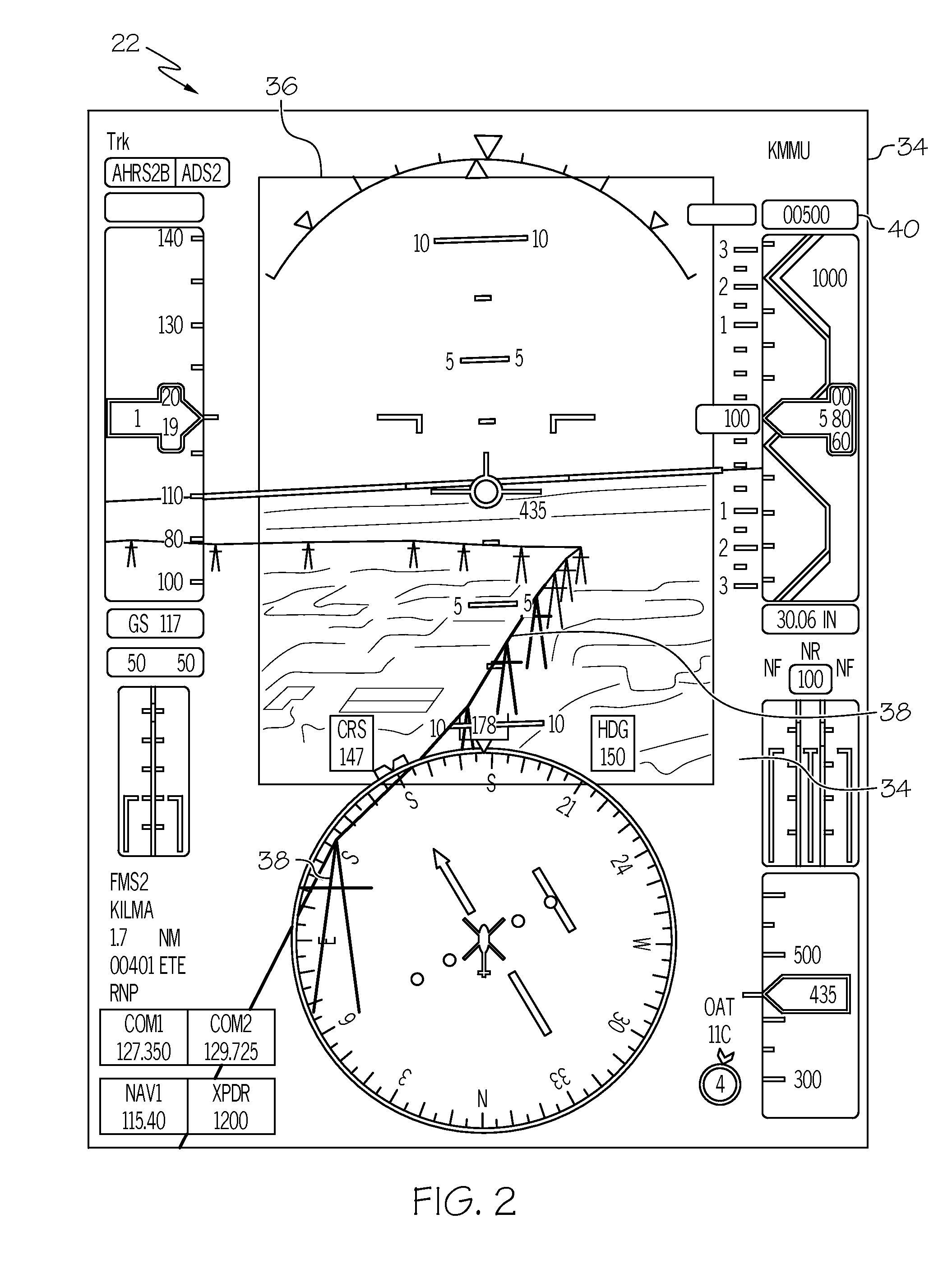
[0016]Various embodiments are directed to systems and methods for enhanced display of obstacles in a combined vision display. Such systems and methods bring selected obstacle images to the fron...


PUM


Abstract

Systems and methods for enhanced display of obstacles in a combined vision display are provided. The system comprises a display unit and an enhanced vision system configured to generate first signals representative of enhanced vision images. Data storage device contains obstacle data representative of obstacles. Synthetic vision system is configured to selectively retrieve obstacle data from data storage device and generate second signals representative of synthetic vision images of one or more obstacles. Processor is in operable communication with display unit and coupled to receive first and second signals and configured, in response thereto, to: overlay the synthetic vision images of the one or more obstacles over the enhanced vision images and command display unit to display the synthetic vision images of the one or more obstacles overlaid over the enhanced vision images. The overlaid synthetic vision images of the one or more obstacles may be visually highlighted.

Description

TECHNICAL FIELD[0001]The present invention generally relates to vehicle display systems, and more particularly relates to aircraft flight deck displays and systems and methods for enhanced display of obstacles in a combined vision display.BACKGROUND[0002]Many vehicles, such as aircraft, are commonly equipped with one or more vision enhancing systems. Such vision enhancing systems are designed and configured to assist a pilot when flying in conditions that diminish the view from the cockpit. One example of a vision enhancing system is known as a synthetic vision system (hereinafter, “SVS”). A typical SVS is configured to work in conjunction with a position determining unit associated with the aircraft as well as dynamic sensors that sense aircraft altitude, heading, and orientation. The SVS includes or accesses a database containing information relating to the topography along the aircraft's flight path, such as information relating to the terrain and known man-made and natural obsta...

Claims


Application Information

Patent Timeline
Patent Type & Authority Applications(United States)
IPC IPC(8): G06T19/00B64D45/00
CPCB64D45/00G06T19/00G01C23/005Y02B10/30
Inventor FEYEREISEN, THEA L.HE, GANGSUDDRETH, JOHN G.VERVERS, PATRICIA MAY
Owner HONEYWELL INT INC
Why Eureka
Try Eureka