Image recording apparatus

a technology of image recording and rotating drum, which is applied in the direction of printing, other printing apparatus, etc., can solve the problems of difficult to efficiently cool the rotating drum, difficult to generate a large amount of high-speed, and liquid to become misaligned on the recording medium, etc., to achieve efficient cooling, effective suppression of air flow, and improved cooling efficiency of the rotating drum

Active Publication Date: 2014-09-18
SEIKO EPSON CORP
View PDF2 Cites 9 Cited by
  • Summary
  • Abstract
  • Description
  • Claims
  • Application Information

AI Technical Summary

Benefits of technology

[0015]In this respect, the image recording apparatus may be configured so that the plurality of the air holes are disposed in the radial direction between the inner surface of the hollow cylinder and the shaft member. Moreover, the image recording apparatus may be configured so that the plurality of air holes are disposed also in the axial direction. Because the plurality of air holes are disposed in this manner, the supporting members can effectively suppress blocking of the air flow, so that a large amount of the high-speed air flow can be generated in the hollow portion of the rotating drum, whereby cooling efficiency of the rotating drum can be improved.
[0016]In this respect, the image recording apparatus may be configured so that, from the above mentioned viewpoint in which the hollow cylinder of the rotating drum is efficiently cooled, the auxiliary heat dissipation member is also disposed on the inner surface of the hollow cylinder of the rotating drum in addition to the supporting members. In such a configuration, the air flow can sufficiently impinge on the auxiliary heat dissipation member disposed on the hollow cylinder, so that the hollow cylinder can exchange heat via the auxiliary heat dissipation member with a large amount of the high-speed air flow, whereby the hollow cylinder can be efficiently cooled.
[0017]Then, the image recording apparatus may be configured so that the auxiliary heat dissipation member is formed in the shape of a ring that extends over the entire periphery in the peripheral direction on the inner surface of the hollow cylinder. The auxiliary heat dissipation member is disposed in this manner to be able to promote heat exchange between the air flow and the hollow cylinder via the auxiliary heat dissipation member, whereby the hollow cylinder can be efficiently reliably cooled.
[0018]Then, the image recording apparatus may be configured so that the auxiliary heat dissipation member includes a wall surface that is inclined in the direction of the air flow and is disposed on an upstream side in the air flow direction. In such a configuration, because the wall surface is inclined in the direction of the air flow which the auxiliary heat dissipation member includes on an upstream side in the air flow direction, the wall surface of the auxiliary heat dissipation member can suppress blocking of the air flow.
[0019]Moreover, the image recording apparatus may be configured so that the discharge head further includes a light irradiator that irradiates a liquid having been discharged onto the recording medium with light, the liquid is a photo-curable liquid which generates heat when it is cured by irradiation with light, and the light irradiator irradiates a portion of the recording medium that is guided around the rotating drum with light. In such an image recording apparatus, the heat generated when the photo-curable liquid is cured heats the rotating drum, resulting in variation of the gap between the rotating drum and the discharge head. In this case, the apparatus has the above-mentioned configuration according to an aspect of the invention, so that a large amount of the high-speed air flow is generated in the hollow portion of the rotating drum, whereby the cooling efficiency of the rotating drum can be preferably improved.
[0020]In particular, if the light irradiator irradiates a portion of the recording medium that is guided around the rotating drum with light, heat is generated when the photo-curable liquid is cured. The heat heats the rotating drum, thereby causing the gap between the rotating drum and the discharge head to vary, which becomes a serious problem. In this case, the apparatus has the above-mentioned configuration according to an aspect of the invention, so that cooling efficiency of the rotating drum can be highly preferably improved.

Problems solved by technology

In such an image recording apparatus, when the rotating drum is heated by the heat source in the apparatus, the rotating drum thermally expands, which causes the gap between the rotating drum and the discharge head to vary, which in turn may cause the liquid to become misaligned on the recording medium.
Under these circumstances, it is not always easy to generate a large amount of high-speed air flow that is intended to pass through the hollow portion of the rotating drum and it can be difficult to efficiently cool the rotating drum.
As mentioned above, heating of the rotating drum becomes a problem when the heated rotating drum thermally expands, the gap between the rotating drum and the discharge heads may vary.
In particular, expansion of the outer surface of the rotating drum considerably affects the gap between the rotating drum and the discharge head.
The heat heats the rotating drum, thereby causing the gap between the rotating drum and the discharge head to vary, which becomes a serious problem.

Method used


Image

  • Image recording apparatus
  • Image recording apparatus
  • Image recording apparatus

Examples


Embodiment Construction

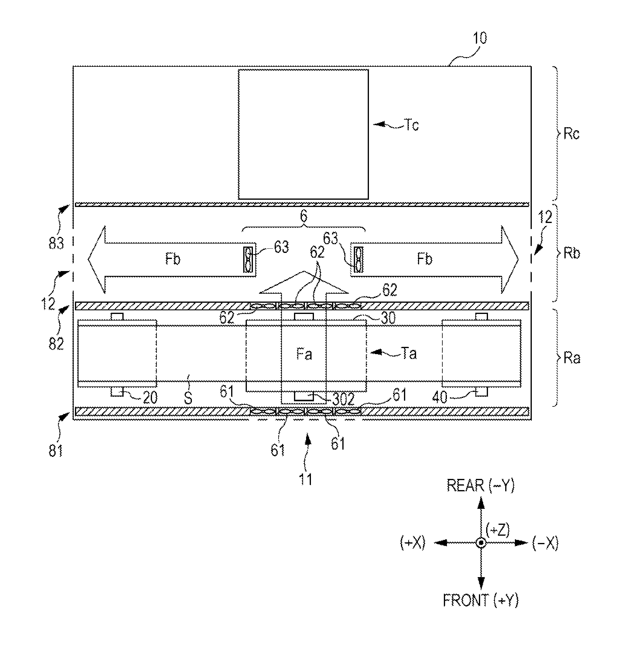
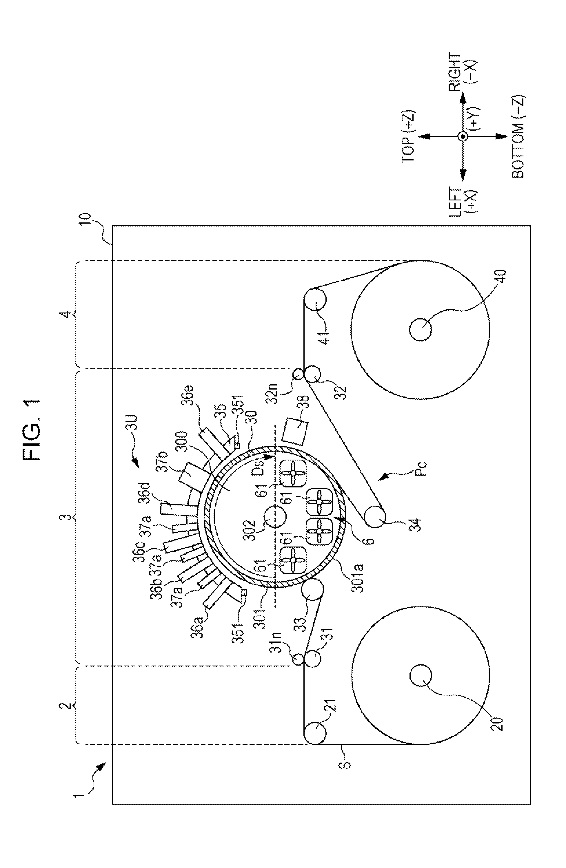
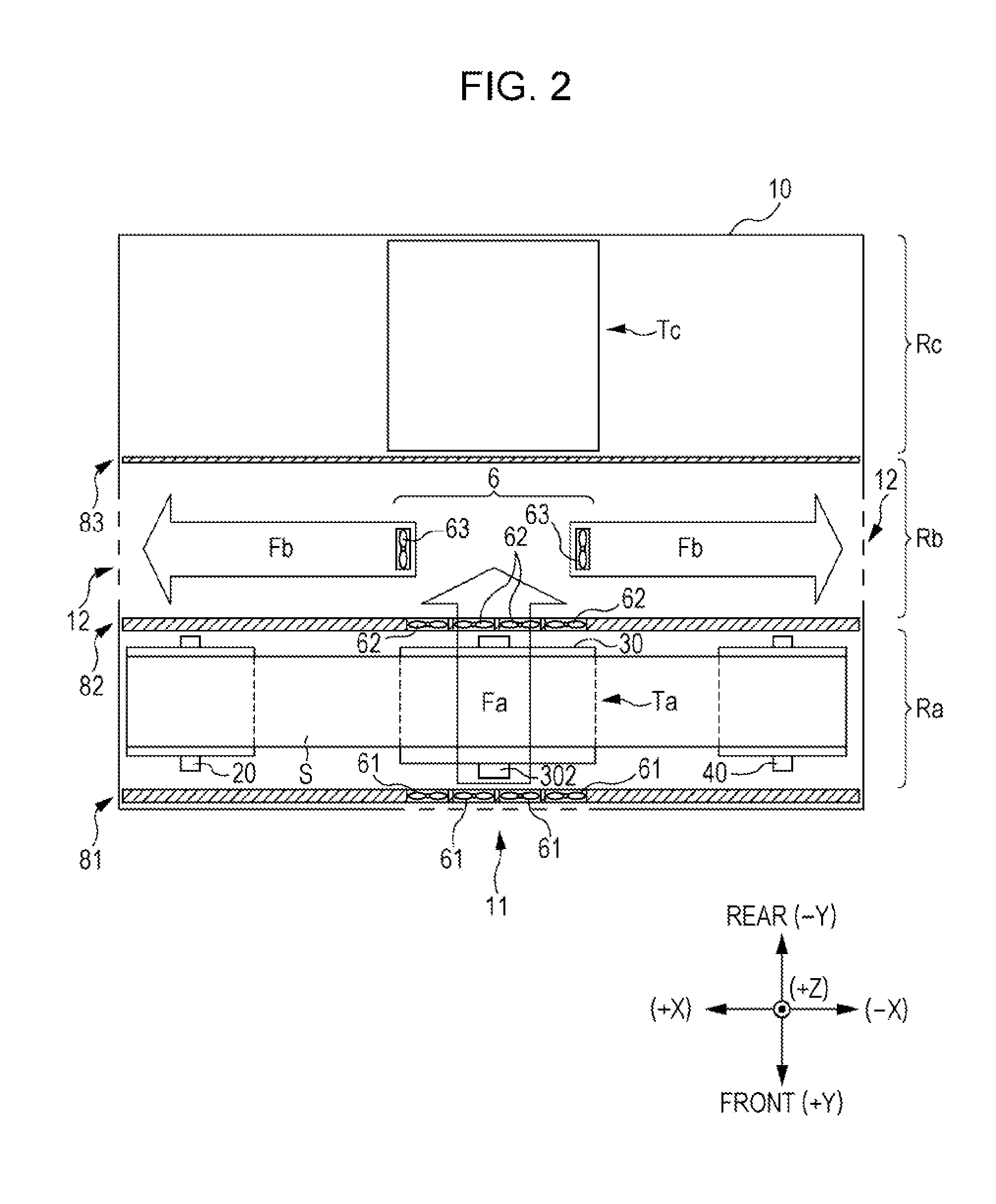
[0028]FIG. 1 is a front view schematically illustrating a schematic configuration of a printing apparatus to which the invention is applicable. An XYZ orthogonal coordinate system corresponding to a left-right direction X, a front-rear direction Y, and a vertical direction Z of a printing apparatus 1 is shown in FIG. 1 and other figures as necessary for clarity of the positional relationships between various components of the apparatus.

[0029]The printing apparatus 1 includes a feeding section 2, a processing section 3, and a winding section 4 arranged in the left-right direction X. These functional portions 2, 3, and 4 are accommodated in a housing member 10 (a casing). The feeding section 2 and the winding section 4 include a feeding shaft 20 and a winding shaft 40, respectively. A sheet S (a web) has both ends wrapped into rolls around the feeding shaft 20 and the winding shaft 40, respectively, and is stretched between the feeding shaft 20 and the winding shaft 40. The sheet S st...


PUM


Abstract

An image recording apparatus includes: a rotating drum including a hollow cylinder around which a recording medium is guided while the rotating drum rotates; a discharge head that discharges liquid onto the recording medium guided around the outer surface of the rotating drum; and an air flow generator that generates an air flow that passes through the inside of the hollow cylinder of the rotating drum. The rotating drum further includes, in the hollow cylinder, a shaft member that has an axis identical to a rotation axis of the rotating drum and supporting members that are plate-shaped and that extend from the shaft member in the radial direction of the rotating drum and support the hollow cylinder, and the rotating drum rotates in a rotation direction about the shaft member. Each of the supporting members includes at least one air hole penetrating therethrough in the rotation direction.

Description

BACKGROUND[0001]1. Technical Field[0002]The present invention relates to an image recording apparatus which discharges liquid from a discharge head and records an image on a recording medium supported on an outer surface of a rotating drum. In particular, the invention relates to a technique for cooling the rotating drum.[0003]2. Related Art[0004]U.S. Pat. No. 5,502,476 describes a printer which discharges an ink from a print head onto an outer surface of a drum to record an image. The printer prints an image on a print medium by cooling and curing ink deposited on the drum by using the drum and transferring the ink to a print medium that forms a nip with the drum. Moreover, in order to effectively cool the ink by using the drum, the drum is cooled by air flow generated using a fan. Specifically, a fan facing the hollow portion of the drum in the axial direction of the drum generates an air flow that passes through the hollow portion of the drum in the axial direction, whereby the d...

Claims


Application Information

Patent Timeline
Patent Type & Authority Applications(United States)
IPC IPC(8): B41J29/377B41J11/00
CPCB41J11/002B41J29/377B41J11/0021B41J11/00214
Inventor SUZUKI, MANABU
Owner SEIKO EPSON CORP
Why Eureka
Try Eureka