Liquid crystal display device and electronic apparatus provided therewith

a technology of electronic equipment and liquid crystal display, which is applied in the direction of optics, instruments, optical light guides, etc., can solve problems such as blurred images, and achieve the effects of reducing the directional dependence of light emitting, reducing blurring of images, and reducing light emission

Inactive Publication Date: 2014-09-18
JAPAN DISPLAY INC
View PDF1 Cites 2 Cited by
  • Summary
  • Abstract
  • Description
  • Claims
  • Application Information

AI Technical Summary

Benefits of technology

[0012]In the liquid crystal display device having the aforementioned structure and the electronic apparatus such a liquid crystal display device, it is possible to dispose the anisotropic scattering member between the second substrate and the polarization plate. Thereby, since there is no need to dispose the polarization plate between the second substrate and the anisotropic scattering member, a distance between the second substrate and the anisotropic scattering member can be shorter or closer. Therefore, the light emitted from the second substrate can directly enter the anisotropic scattering member. Therefore, it is possible to prevent the light emitted from the second substrate from expanding in the display surface and thus reduce the blurring of images. It is also possible to set the scattering axis direction to the same direction as the main view angle direction. Thereby, the anisotropic scattering member can scatter the light entering the anisotropic scattering member toward the main view angle direction. Therefore, the anisotropic scattering member can reduce the light emitting toward a predetermined direction without scattering, and thus reduce the directional dependency of light emitting from the anisotropic scattering member. Thereby, the blurring of images can be reduced and thus the directional dependency of light can be reduced. Therefore, the visibility can be improved.

Problems solved by technology

Thereby, the reflected light is likely to expand in a surface or plane and it causes a blurred image.

Method used


Image

  • Liquid crystal display device and electronic apparatus provided therewith
  • Liquid crystal display device and electronic apparatus provided therewith
  • Liquid crystal display device and electronic apparatus provided therewith

Examples


Embodiment Construction

[0046]The present disclosure will now be described according to the following orders and with reference to the accompanying drawings.

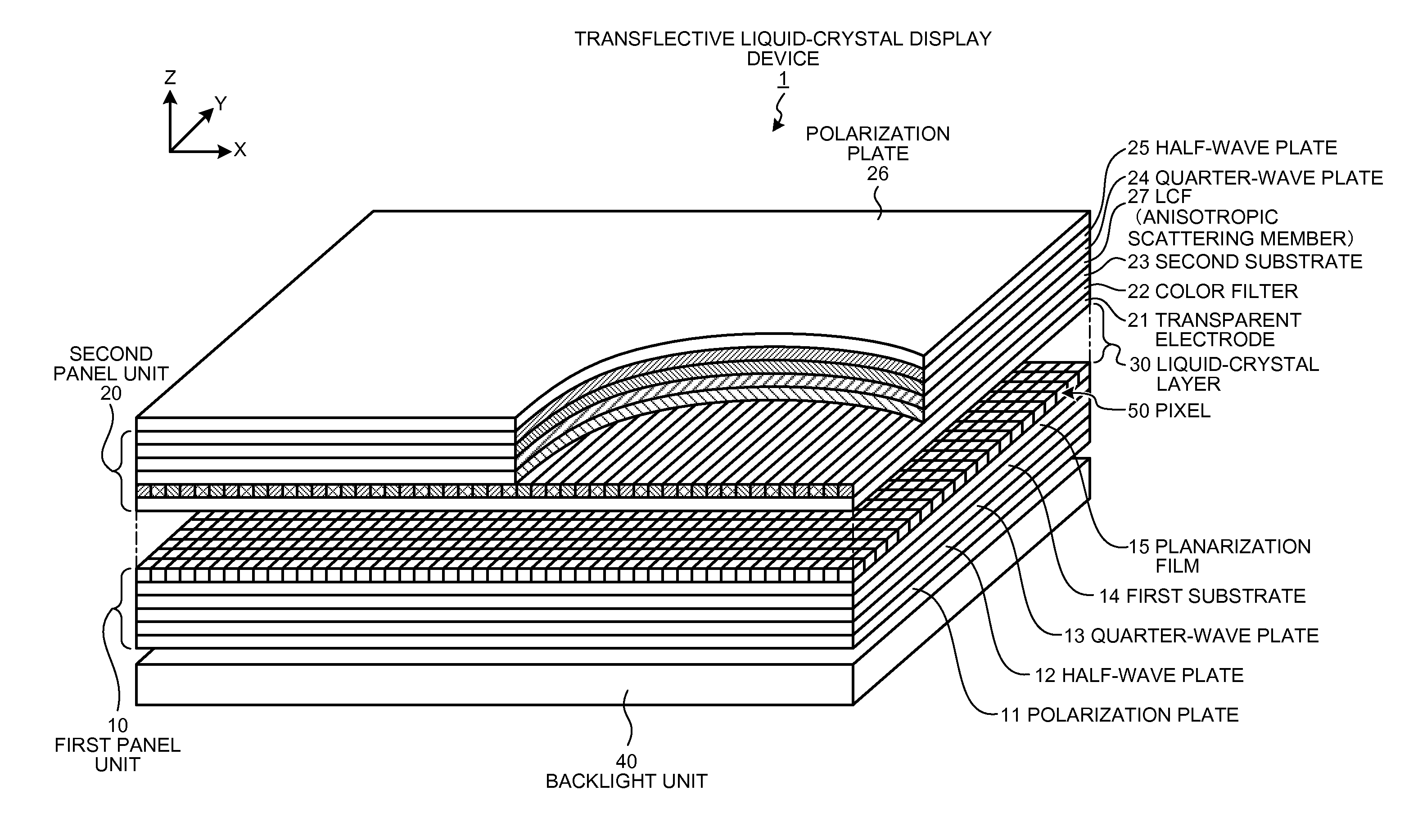
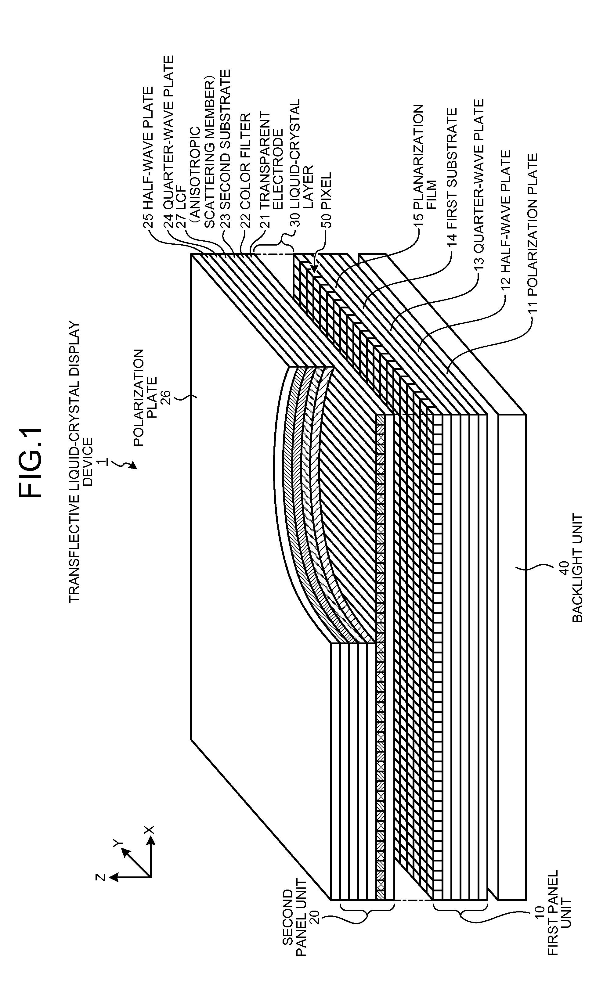
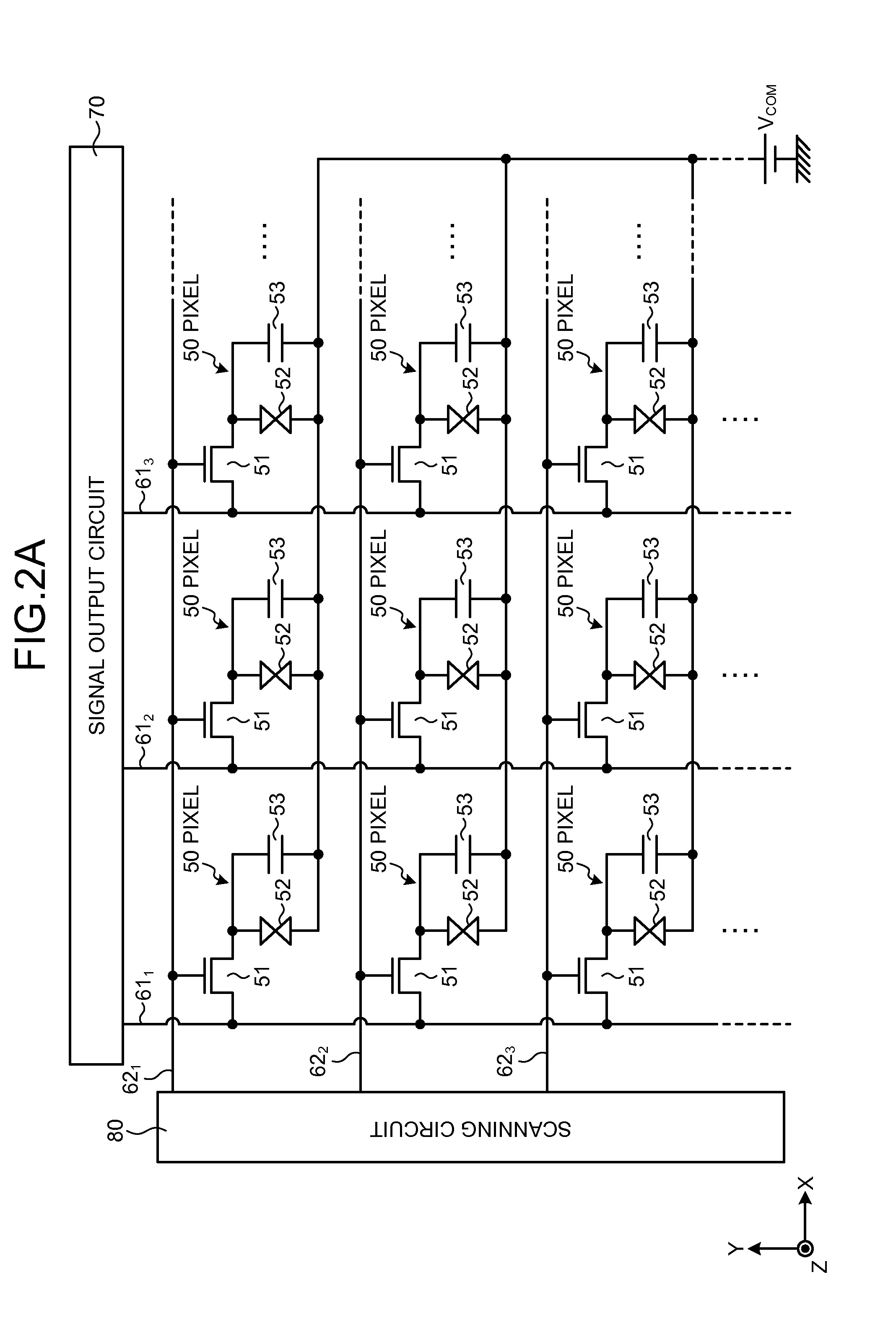
[0047]1. Transflective LCD Device[0048]1-1. Transflective LCD device for Color Display[0049]1-2. Fundamental Pixel Circuit[0050]1-3. Pixel and Sub-pixel[0051]1-4. Electrode Structure of Pixel portion[0052]1-5. Driving Scheme of LCD Panel[0053]1-6. Anisotropic Scattering Member[0054]1-7. Backlight Unit

[0055]2. Electronic apparatuses

[0056]3. Configuration of Present Disclosure

[0057]

[0058]A technology in the present disclosure can be applied to a flat panel type display device. Examples of the flat panel type display device include a display device using a liquid crystal display (LCD) panel, a display device using electro luminescence (EL) display panel, a display panel using a plasma display (PD) panel, and so on.

[0059]These flat panel type display devices can be classified into transmissive type and reflective type, according to display schemes. The tec...


PUM

PropertyMeasurementUnit
angleaaaaaaaaaa
angleaaaaaaaaaa
inclined angleaaaaaaaaaa

Abstract

A liquid crystal display device includes a first substrate provided with a reflective electrode, a second substrate provided with a transparent electrode oppositely disposed to the reflective electrode, a liquid crystal layer disposed between the first second substrates, a polarization plate oppositely disposed to the first substrate with an interposition of the second substrate, and an anisotropic scattering member disposed between the second substrate and the polarization plate. A main view angle direction is set as a predetermined direction intersecting a display surface. The anisotropic scattering member has a scattering center and scatters light traveling along a scattering axis direction which is a direction having a predetermined angle range centered around the scattering center. The scattering axis direction coincides with the main view angle direction.

Description

CROSS REFERENCES TO RELATED APPLICATIONS[0001]The present application claims priority to Japanese Priority Patent Application JP 2013-051957 filed in the Japan Patent Office on Mar. 14, 2013, the entire content of which is hereby incorporated by reference.BACKGROUND[0002]1. Field of the Invention[0003]The present invention relates to a liquid crystal display (LCD) device and an electronic apparatus provided therewith.[0004]2. Description of the Related Art[0005]As a display device, there is known a reflective type display device for displaying an image by using reflected light of incident light entered from outside, as well as a transmissive type display device for displaying an image using transmitted light of backlight from a rear surface of a screen. The reflective type display device has advantageous features such as low power consumption and viewable screen or monitor even in bright environment. Furthermore, as a display device having a feature of the reflective type display de...

Claims


Application Information

Patent Timeline
Patent Type & Authority Applications(United States)
IPC IPC(8): G02F1/1335F21V8/00
CPCG02F1/133504G02F1/133528G02B6/0011G02B5/0257G02B5/0289G02F1/133524G02F1/133555G02F1/133541G02F1/133638
Inventor MITSUI, MASASHITAMAKI, MASAYAFUKUNAGA, YOKO
Owner JAPAN DISPLAY INC
Why Eureka
Try Eureka