Specular object scanner for measuring reflectance properties of objects

a technology of reflectance properties and scanners, applied in the field of object scanners, can solve the problems of not producing independent measurements of diffuse and specular reflectance parameters, requiring high-power laser equipment, and unable to achieve significant surface reflectance detail

Active Publication Date: 2014-09-18
UNIV OF SOUTHERN CALIFORNIA
View PDF1 Cites 35 Cited by
  • Summary
  • Abstract
  • Description
  • Claims
  • Application Information

AI Technical Summary

Benefits of technology

[0010]In one or more aspects of the disclosure, examples are provided for an apparatus to measure surface orientation maps of an object. The apparatus may include a light source configured to illuminate the object with a controllable field of illumination. One or more driver circuits may be configured to drive the light source with modulated signals to generate the controllable field of illumination. A processor may be configured to generate control signals to control the one or more driver circuits to cause the one or more driver circuits to drive the light source with the modulated signals. The controllable field of illumination comprises limited-order Spherical Harmonics (SH) and Fourier Series (FS) illumination patterns with substantially similar polarization, wherein the SH and FS illumination patterns are used with different light sources. The light source may include a plurality of light-emitting elements such as light-emitting diodes (LEDs) mounted on a source assembly, such as an arc-shaped source assembly, which is formed to have a semi-circular arc shape or a polygon arc shape, and can rotate around the object to sweep a partial sphere surface or a full sphere surface around the object. The rotating arc-shaped source assembly can illuminate the object with the SH illumination patterns.

Problems solved by technology

None of these techniques, however, produces independent measurements of diffuse and specular reflectance parameters for each observed surface point, and thus may miss important surface reflectance detail.
EGSR, 91-98 recorded diffuse and specular reflectance behavior of objects with high angular resolution using a surrounding spherical dome and a laser to excite the various surface BRDFs through Helmholz reciprocity, but achieved limited spatial resolution and required a high-powered laser equipment.
Unfortunately, the use of an LED sphere with limited resolution made the reflectance analysis applicable only to relatively rough specular materials such as human skin, and the use of polarization for component separation becomes complicated for metallic surfaces and near the Brewster angle.
Highly specular objects have long posed problems for image-based shape reconstruction Blake, A., and Brelstaff, G.
IEEE International Conference on Computer Vision, 591-596 pro-posed a multi-view voxel carving technique based on reflected observations of a calibrated world pattern, but achieved very low resolution results.
These techniques work well in principle but are limited to scanning small flat objects that are covered by the illumination from an extended source.

Method used


Image

  • Specular object scanner for measuring reflectance properties of objects
  • Specular object scanner for measuring reflectance properties of objects
  • Specular object scanner for measuring reflectance properties of objects

Examples


Embodiment Construction

[0034]Illustrative embodiments are now described. Other embodiments may be used in addition or instead. Details that may be apparent or unnecessary may be omitted to save space or for a more effective presentation. Some embodiments may be practiced with additional components or steps and / or without all of the components or steps that are described.

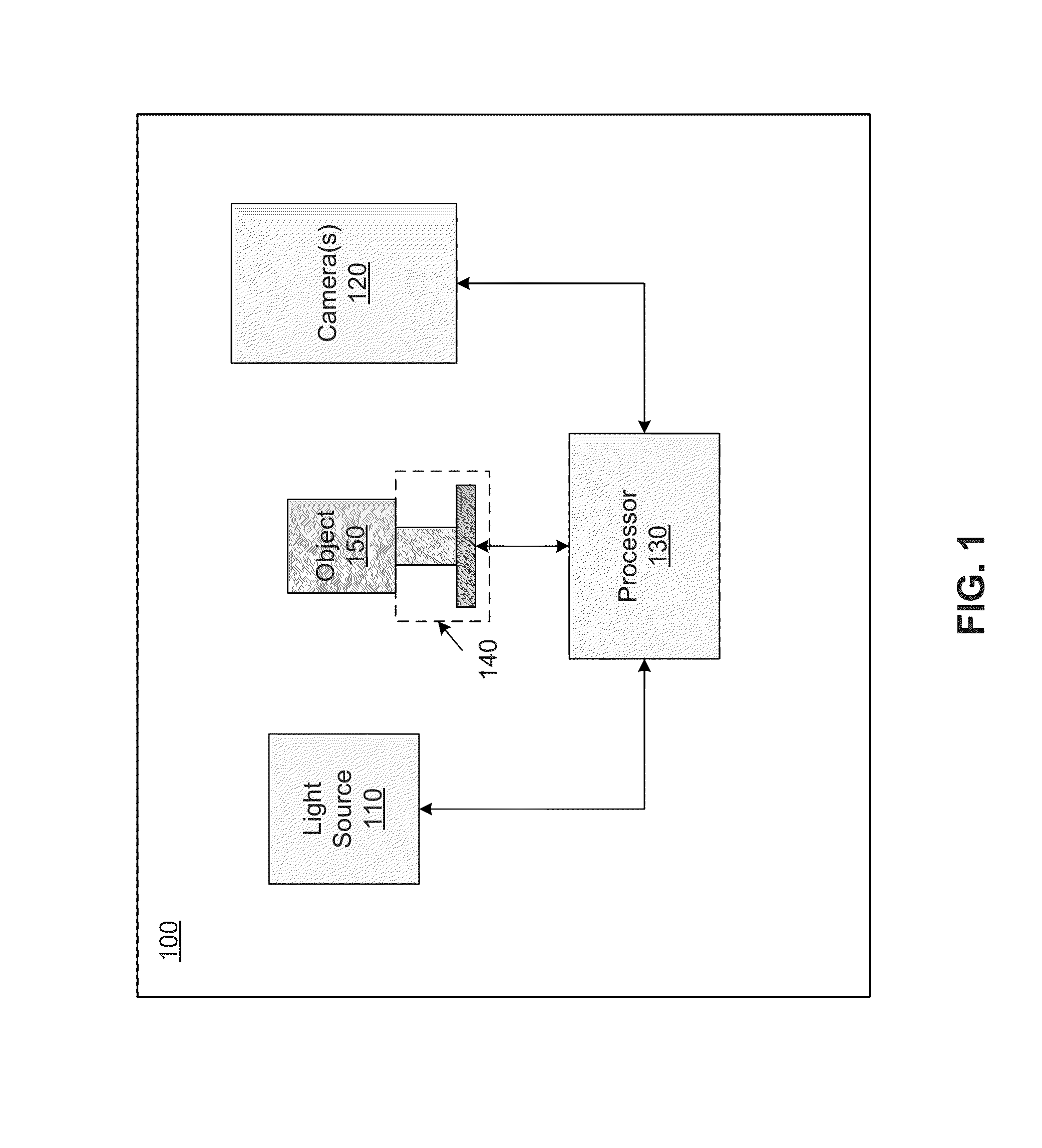
[0035]FIG. 1 is a conceptual diagram illustrating an example of a system 100 for measuring reflectance properties of an object in accordance with some implementations of the subject technology. The system 100 includes a light source 110, one or more cameras 120, a processor 130, and a platform 140, on which an object 150 can be placed. The light source 110 can illuminate the object 150 (e.g., a specular object) with a controllable field of illumination using limited-order (e.g., up to 5th order) Spherical Harmonics (SH) or Fourier Series (FS) illumination patterns. The light source 110 may include one or more driver circuits that can drive...


PUM

PropertyMeasurementUnit
specular roughness parametersaaaaaaaaaa
specular roughnessaaaaaaaaaa
roughnessaaaaaaaaaa

Abstract

An apparatus to measure surface orientation maps of an object may include a light source that is configured to illuminate the object with a controllable field of illumination. One or more cameras may be configured to capture at least one image of the object. A processor may be configured to process the image(s) to extract the reflectance properties of the object including an albedo, a reflection vector, a roughness, and/or anisotropy parameters of a specular reflectance lobe associated with the object. The controllable field of illumination may include limited-order Spherical Harmonics (SH) and Fourier Series (FS) illumination patterns with substantially similar polarization. The SH and FS illumination patterns are used with different light sources.

Description

CROSS-REFERENCE TO RELATED APPLICATION[0001]This application is based upon and claims priority to U.S. provisional patent application 61 / 783,115 entitled “Specular Object Scanner That Creates Controllable Illumination To Capture Data and Measure Properties Of Translucent, Transparent, And Reflective Objects” filed Mar. 14, 2013, attorney docket number 028080-0849. The entire content of this application is incorporated herein by reference.BACKGROUND[0002]1. Technical Field[0003]This disclosure relates to object scanners, in particular, but not restricted to a specular object scanner for measuring reflectance properties of objects.[0004]2. Description of Related Art[0005]An extensive body of work in the graphics and vision literature addresses the acquisition of geometry and reflectance from images under controlled and uncontrolled lighting conditions. Two recent overviews are Weyrich, T., Lawrence, J., Lensch, H. P. A., Rusinkiewicz, S., and Zickler, T. 2009, Principles of appearance...

Claims


Application Information

Patent Timeline
Patent Type & Authority Applications(United States)
IPC IPC(8): G01N21/47G01N21/01
CPCG01N21/01G01N21/47G01N21/55G01B11/25G01B11/30
Inventor DEBEVEC, PAUL E.YU, XUEMINGFYFFE, GRAHAM LESLIEGHOSH, ABHIJEET
Owner UNIV OF SOUTHERN CALIFORNIA
Why Eureka
Try Eureka