Method and appartus for signal interference processing

a signal interference and processing method technology, applied in the direction of transmission monitoring, receiver monitoring, frequency-division multiplex, etc., can solve the problems of affecting the performance of a communication system, reducing throughput, and dropping calls

Active Publication Date: 2014-09-18
ILLINOIS SUPERCONDUCTOR CORP
View PDF11 Cites 148 Cited by
  • Summary
  • Abstract
  • Description
  • Claims
  • Application Information

AI Technical Summary

Problems solved by technology

In most communication environments involving short range or long range wireless communications, interference from unexpected wireless sources can impact the performance of a communication system leading to lower throughput, dropped calls, reduced bandwidth which can cause traffic congestion, or other adverse effects, which are undesirable.
Any electronic appliance that generates electromagnetic waves such as, for example, a computer, a set-top box, a child monitor, a wireless access point (e.g., WiFi, ZigBee, Bluetooth, etc.) can be a source of interference.
Due to such noise like characteristics of the signal, a particular measurement of a narrowband channel power gives no predictive power as to what the next measurement of the same measurement channel may be.
Due to such noise like characteristic of DSSS signal, a particular measurement of a narrowband channel power gives no predictive power as to what the next measurement of the same measurement channel may be.
However, the higher the number m is, the higher is the delay in determining whether a particular DSSS signal had an interference present in it, subsequently, resulting in a longer delay before a filter is applied to the DSSS signal to remove the interference signal.
However, since each transmission consists of unknown RB allocations with unknown durations, such a detection principle can only be applied separately for each individual RB within a frequency and specific time domain.
If a particular RB is not used for LTE transmission at the time of detection, the RF spectrum will present a thermal noise which adheres to the characteristics of a spread spectrum signal, similar to a CDMA / UMTS signal.
Since such LTE transmissions do not typically have flat power spectral densities (see FIG. 14), identification of interference as shown in FIG. 15 can be a difficult technical problem.
This step can be used to avoid skewing a baseline average across all frequency increments from being too high, resulting in a threshold calculation that may be too conservative.

Method used


Image

  • Method and appartus for signal interference processing
  • Method and appartus for signal interference processing
  • Method and appartus for signal interference processing

Examples


Embodiment Construction

[0026]The subject disclosure describes, among other things, illustrative embodiments for detecting and mitigating interference signals. Other embodiments are included in the subject disclosure.

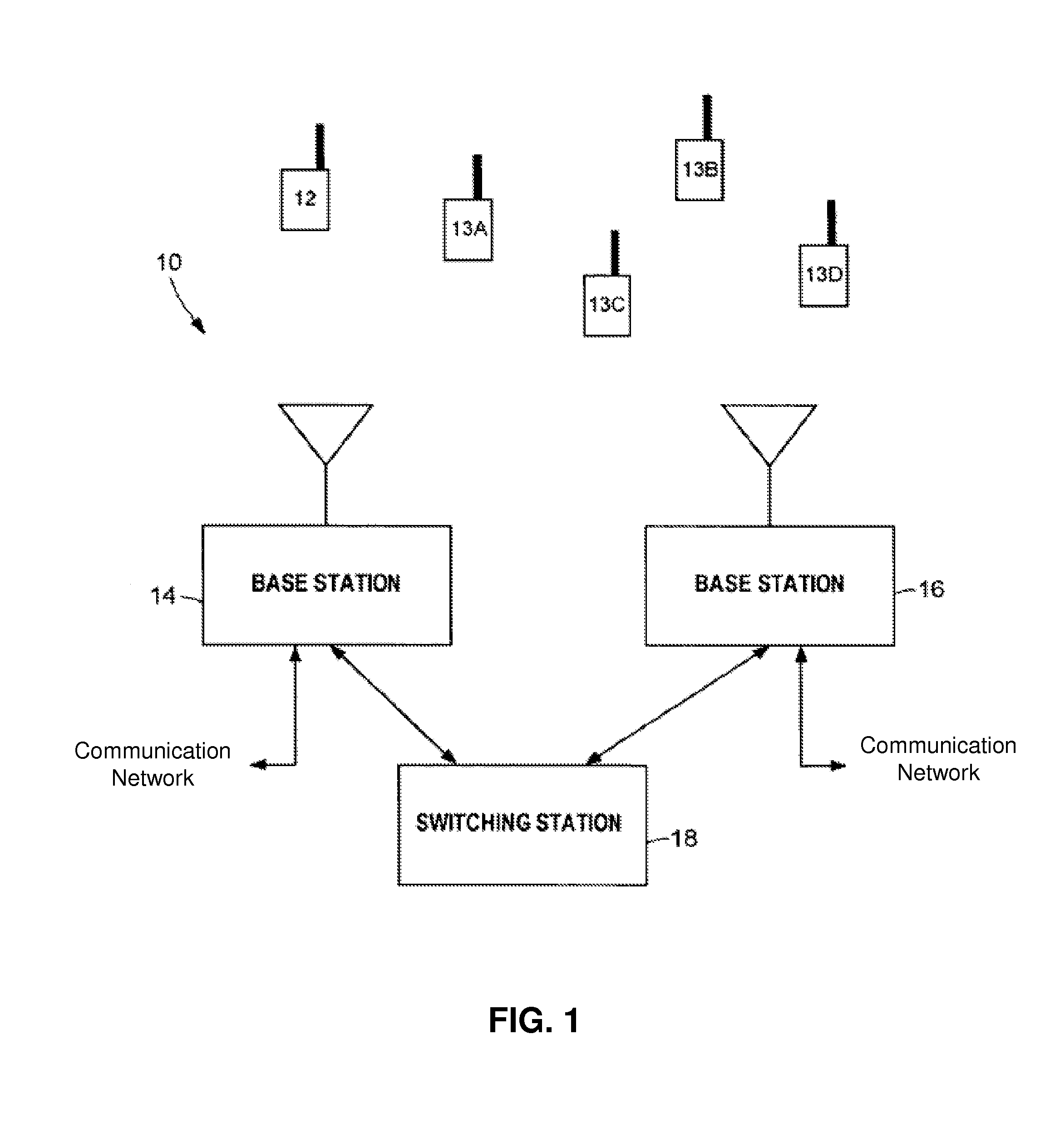
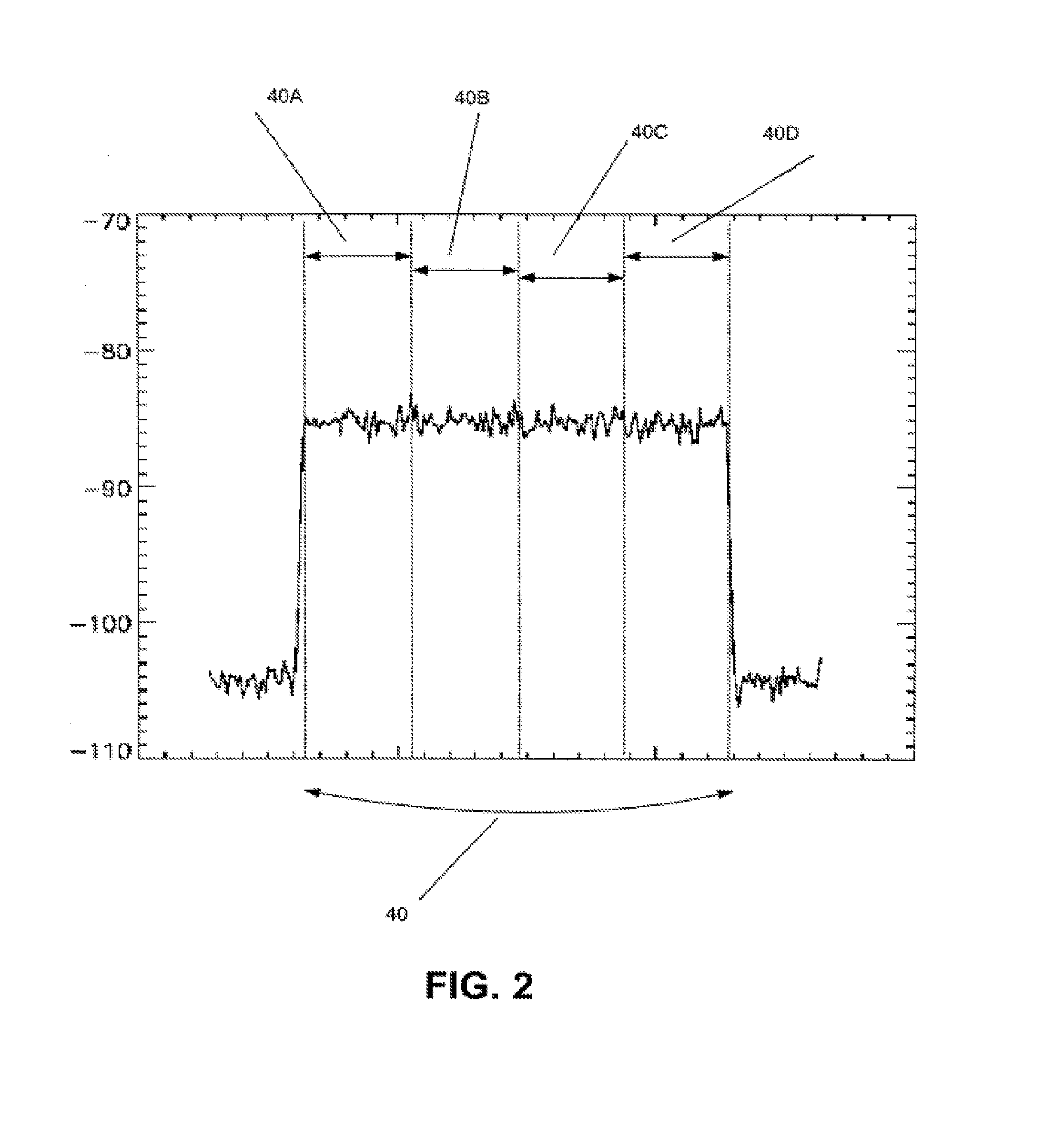
[0027]One embodiment of the subject disclosure includes a method for measuring, by a system comprising a processor, a power level in each of a plurality of resource blocks occurring in a radio frequency spectrum of a wireless communication system, wherein the measuring occurs for a plurality of time cycles to generate a plurality of power level measurements for each resource block, calculating, by the system, a baseline power level for each resource block of the plurality of resource blocks according to at least one of the plurality power level measurements of each resource block to generate a plurality of baseline power levels for the plurality of resource blocks, calculating, by the system, an aggregate baseline power level according to at least a portion of the plurality of baseline power l...


PUM


Abstract

A system that incorporates the subject disclosure may include, for example, a method for measuring a power level in at least a portion of a plurality of resource blocks occurring in a radio frequency spectrum, wherein the measuring occurs for a plurality of time cycles to generate a plurality of power level measurements, calculating a baseline power level according to at least a portion of the plurality of power levels, determining a threshold from the baseline power level, and monitoring at least a portion of the plurality of resource blocks for signal interference according to the threshold. Other embodiments are disclosed.

Description

CROSS-REFERENCE TO RELATED APPLICATIONS[0001]The present application claims the benefit of priority to U.S. Provisional Application No. 61 / 792,184 filed on Mar. 15, 2013, Attorney Docket No. 4400-0022P, entitled, “Method and apparatus for Interference Detection and Mitigation,” which is hereby incorporated herein by reference in its entirety.FIELD OF THE DISCLOSURE[0002]The subject disclosure is related to a method and apparatus for signal interference processing.BACKGROUND[0003]In most communication environments involving short range or long range wireless communications, interference from unexpected wireless sources can impact the performance of a communication system leading to lower throughput, dropped calls, reduced bandwidth which can cause traffic congestion, or other adverse effects, which are undesirable.[0004]Some service providers of wireless communication systems have addressed interference issues by adding more communication nodes, policing interferers, or utilizing ant...

Claims


Application Information

Patent Timeline
Patent Type & Authority Applications(United States)
IPC IPC(8): H04W24/02H04W4/02H04W4/029
CPCH04W24/02H04B1/1036H04B1/71H04L5/0026H04L5/006H04B17/26H04B17/345H04W28/04H04W72/0446H04W72/0453H04W4/023H04B7/2634H04B1/709H04B1/7103H04W24/08H04W4/02H04B17/318H04L5/0007H04W28/0236H04B17/327H04W52/14H04W4/029H04W72/541H04W72/52H04W72/54H04W72/542H04L5/0073H04L41/069H04W24/10H04W40/16H04W16/28H04B2201/709709H04J11/0066H04W52/243H04B17/21H04B17/373H04B2201/709745H04B15/00H04B17/00H04W52/04H04W64/00H04W64/006H04L5/0032
Inventor ABDELMONEM, AMRGALEEV, MIKHAILCORDONE, SEAN S.WANG, ZHIGANGWONG, HOWARDSEOANE, JORGE
Owner ILLINOIS SUPERCONDUCTOR CORP
Why Eureka
Try Eureka