
Mobile phone employing bone conduction device

a bone conduction device and mobile phone technology, applied in the direction of substation equipment, electrical equipment, telephone set construction, etc., can solve the problems of insufficient isolation between the housing and the bone conduction speaker, the entire case vibrating, and the sound leakage, so as to reduce the installation space of the bone conduction device, increase the thickness of the mobile phone body, and reduce the effect of sound leakag

Inactive Publication Date: 2014-09-18
TEMCO JAPAN
View PDF7 Cites 44 Cited by
  • Summary
  • Abstract
  • Description
  • Claims
  • Application Information

AI Technical Summary

Benefits of technology

The present invention allows for a small gap between the bone conduction speaker and the housing or buffering member to prevent contact with other parts during vibration. This results in a smaller space requirement for installation, reduces the need for a thicker housing, and simplifies the assembly process.

Problems solved by technology

In the case where the bone conduction device is to be installed on the body of a mobile phone, fixing it directly to a case of the mobile phone body can cause the entire case to be vibrated, resulting in a so-called sound leak being generated, which can be a problem.
In addition, in the case of the aforementioned configuration, a thin buffering member is used in order to suppress the thickness from being increased, thereby the buffering action by the buffering member being weak, and thus a sufficient isolation between the housing and the bone conduction speaker cannot be secured.
However, the mobile phone using the bone conduction device according to the aforementioned proposal has a configuration in which the recessed portion 43 having a diameter larger than that of the bone conduction device 41 is provided in the housing 42, and inside the recessed portion 43, the bone conduction device 41 is installed through the buffering member 44 disposed in the inner face thereof, thereby presenting a problem that dirt and dust are easily stuck to and accumulated in the gap between the bone conduction device 41 and the inner face of the recessed portion 43.
In addition, there arise a problem that a space for fixing the outside portion of the buffering member 44 to the inner face of the recessed portion 43 is required, and another problem that, in order to stably maintain the space between the bone conduction device 41 and the inner face of the recessed portion 43, a certain contrivance for fixing the outside portion of the buffering member 44 to the inner face of the recessed portion 43 rigidly and permanently is required to be provided.

Method used


Image

  • Mobile phone employing bone conduction device
  • Mobile phone employing bone conduction device
  • Mobile phone employing bone conduction device

Examples


first embodiment

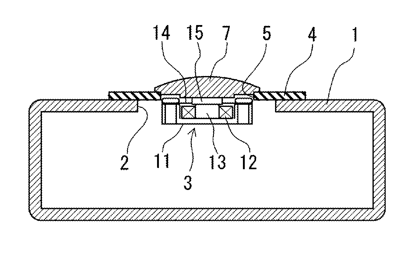
[0026]FIG. 1 illustrates the present invention, and in this embodiment, the buffering member 4 is an annular plate (generally, an annular disk, and this holds true also for an annular plate in later-described respective embodiments) in which there is formed a central hole 5 (generally, a round hole, and this holds true also for a central hole in the later-described respective embodiments) having a diameter slightly smaller than the outer diameter of the bone conduction device 3, a half portion on the outer edge side of the buffering member 4 being securely set on the upper edge portion of the opening 2 of the housing 1, and the outer edge portion of the abutting member 7 being securely set on the upper edge portion of the central hole 5 in the buffering member 4.

[0027]The bone conduction speaker 3 to be used here is of so-called external magnet type, in which, for example, particularly as shown in FIG. 5, a diaphragm 14 is stationarily fixed on a yoke 11 with a slight gap being main...

second embodiment

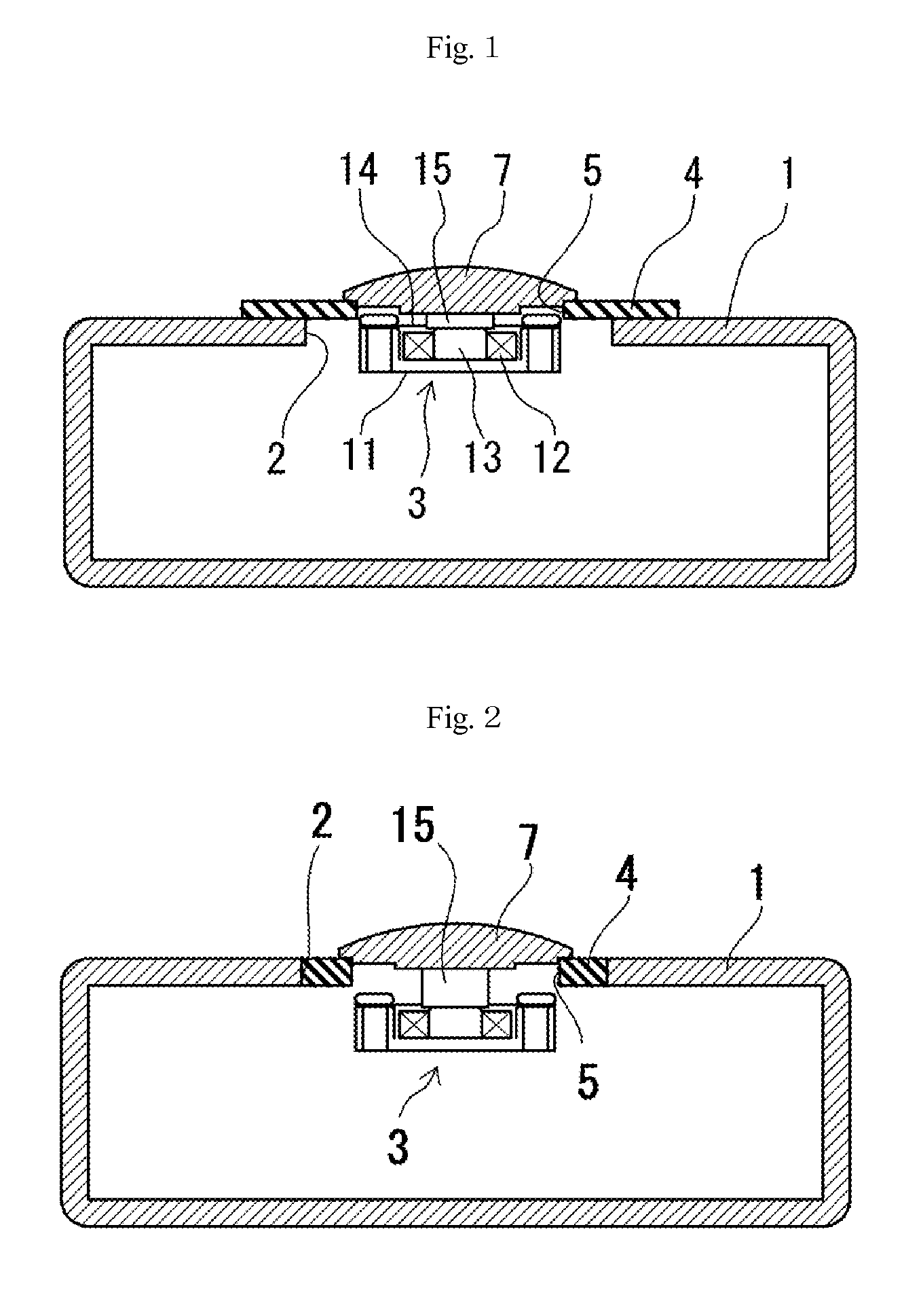
[0028]FIG. 2 illustrates the present invention, and in this embodiment, the buffering member 4 is an annular plate in which there is formed a central hole 5 having a diameter slightly smaller than the outer diameter of the bone conduction device 3, the buffering member 4 being fitted into the opening 2 in the housing 1, and the outer edge portion of the abutting member 7 is securely set on the upper edge portion of the central hole 5 in the buffering member 4.

third embodiment

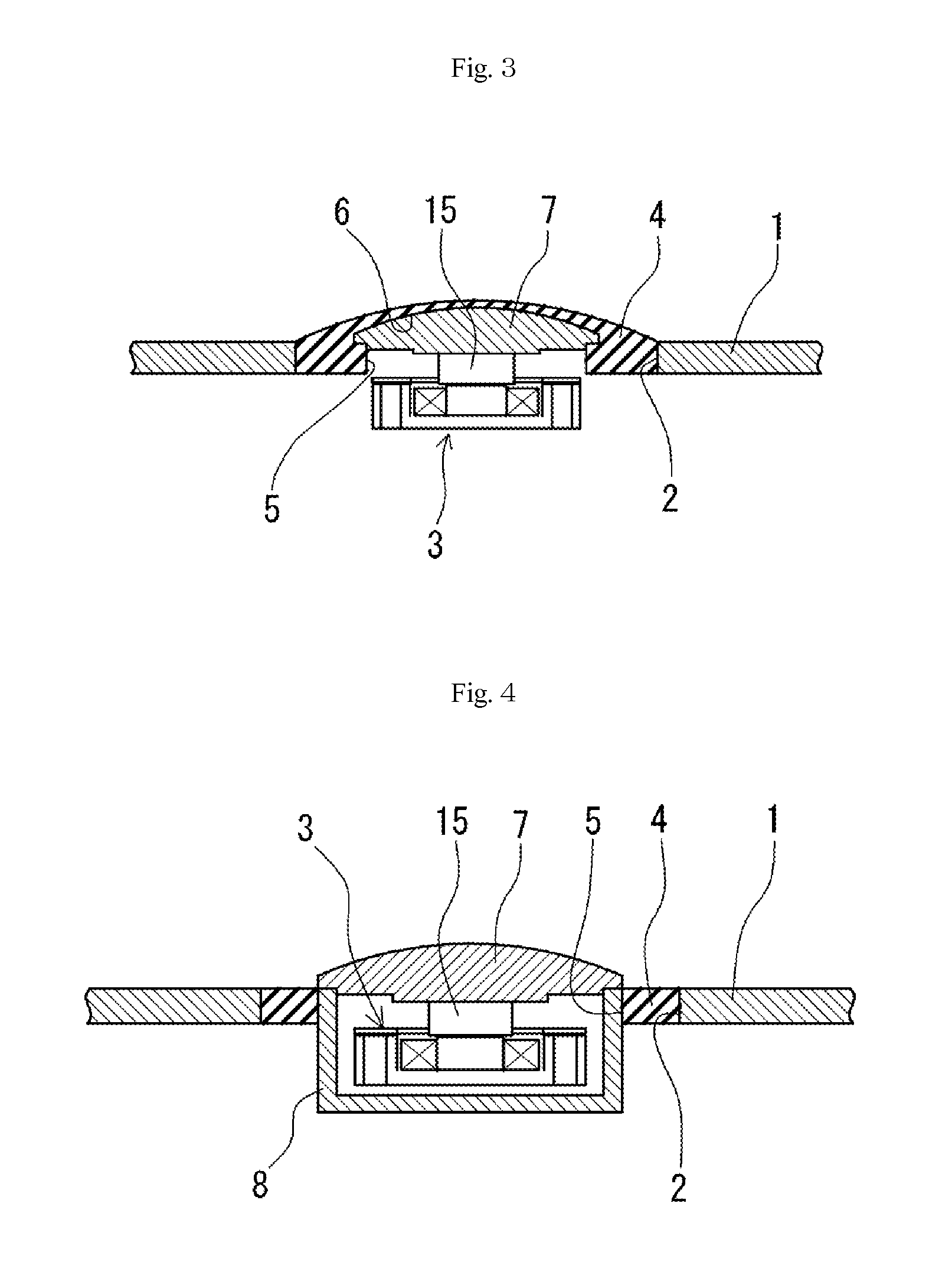
[0029]FIG. 3 illustrates the present invention, and in this embodiment, the buffering member 4 is a dish-like piece in which there are formed a central hole 5 having a diameter slightly smaller than the outer diameter of the bone conduction device 3, and an abutting member fitting space 6 in communication with the central hole 5. This buffering member 4 is fitted into the opening 2 in the housing 1 with an abutting member 7 being tightly fitted into the abutting member fitting space 6.

[0030]FIG. 4 illustrates a fourth embodiment of the present invention, and in this embodiment, the buffering member 4 is an annular plate in which there is formed a central hole 5 having a diameter slightly smaller than the outer diameter of the bone conduction device 3, and which is fitted into the opening 2 in the housing 1. The bone conduction speaker 3 is housed in a device case 8 with a gap being maintained between the peripheral face and bottom face thereof and the device case 8, an abutting memb...


PUM


Abstract

One surface of a housing is furnished with an opening larger in diameter than a bone conduction device placed therein. A cushioning material is arranged on the inside surface of the opening, and an abutting member secured to a plate yoke constituting the bone conduction device is supported on the cushioning material, such that the top surface thereof is positioned slightly above the surface of the housing. The cushioning material is an annular disk in which is formed a center hole slightly smaller in diameter than the outside diameter of the bone conduction device. The outside peripheral half of the cushioning material is secured resting on the upper edge of the opening of the housing, and the outside edge of the abutting member is secured resting on the upper edge of the center hole of the cushioning material.

Description

FIELD OF TECHNOLOGY[0001]The present invention relates to a mobile phone using a bone conduction device, and more particularly, to a mobile phone using a bone conduction device as a speaker and / or microphone, the bone conduction device being applied to the head of a user in service for sounding a received voice or picking up a bone conducted sound.BACKGROUND[0002]In the case where the bone conduction device is to be installed on the body of a mobile phone, fixing it directly to a case of the mobile phone body can cause the entire case to be vibrated, resulting in a so-called sound leak being generated, which can be a problem. In order to solve this problem, with a mobile phone using a conventional bone conduction speaker, the bone conduction speaker 31 has been installed therein, being accommodated in a recessed portion 33 provided in an appropriate area of a housing 32 along the direction of the thickness thereof through a buffering member 34 for securing isolation from the housing...

Claims


Application Information

Patent Timeline
IPC IPC(8): H04M1/03
CPCH04M1/03H04R1/025H04R2460/13H04R2499/11
Inventor FUKUDA, MIKIO
Owner TEMCO JAPAN
Features
  • Generate Ideas
  • Intellectual Property
  • Life Sciences
  • Materials
  • Tech Scout
  • Unparalleled Data Quality
  • Higher Quality Content
  • 60% Fewer Hallucinations
Learn More