
Rehabilitation device and method

a technology of rehabilitation device and rehabilitation method, applied in the field of rehabilitation device, can solve the problems of affecting the rehabilitation and affecting the rehabilitation of individuals, so as to reduce the time and cost of physical therapists/rehabilitation technicians

Inactive Publication Date: 2014-09-18
BOYETTE ROBERT B +1
View PDF3 Cites 25 Cited by
  • Summary
  • Abstract
  • Description
  • Claims
  • Application Information

AI Technical Summary

Benefits of technology

The present invention relates to a rehabilitation device that can be used by people of different heights and degrees of joint mobility. The device has sensors and a microprocessor to monitor input variables and record performance data. The device also has a motor resistance unit that can help to drive the pedals or provide resistance while a user is pedaling. The device can automatically adjust system parameters to optimal values for each user and continuously monitor the patient's progress in real time. The invention reduces physical therapist / rehabilitation technician time and cost due to a fully automatic operation.

Problems solved by technology

After an injury or surgery, these values can be minimal as injury or surgery often results in a substantial loss in range of motion.
Stationary bicycles can be problematic for these individuals since they have such a limited range of motion and / or a decreased amount of strength or muscle tone.
Since these individuals may not be able to fully achieve this rotation they must begin to pedal and then change direction when they have reached their range of motions limits.
Additionally, since the pedals are in a fixed location, once an individual has begun to regain their range of motion there is a limit to how far they are able to progress.
The fixed pedal throw does not allow multiple users to achieve the same benefits.
One user may have shorter legs and / or a more severe injury and the pedal may be too long to rotate comfortably, whereas another individual may be taller or less injured and need a longer pedal throw to achieve the required amount of flexion for optimal recovery.

Method used


Image

  • Rehabilitation device and method
  • Rehabilitation device and method
  • Rehabilitation device and method

Examples


Embodiment Construction

[0041]The preferred embodiments of the present invention will now be described with reference to the drawings. Identical elements in the various figures are identified, as far as possible, with the same reference numerals. Reference will now be made in detail to embodiments of the present invention. Such embodiments are provided by way of explanation of the present invention, which is not intended to be limited thereto. In fact, those of ordinary skill in the art may appreciate upon reading the present specification and viewing the present drawings that various modifications and variations can be made thereto without deviating from the innovative concepts of the invention.

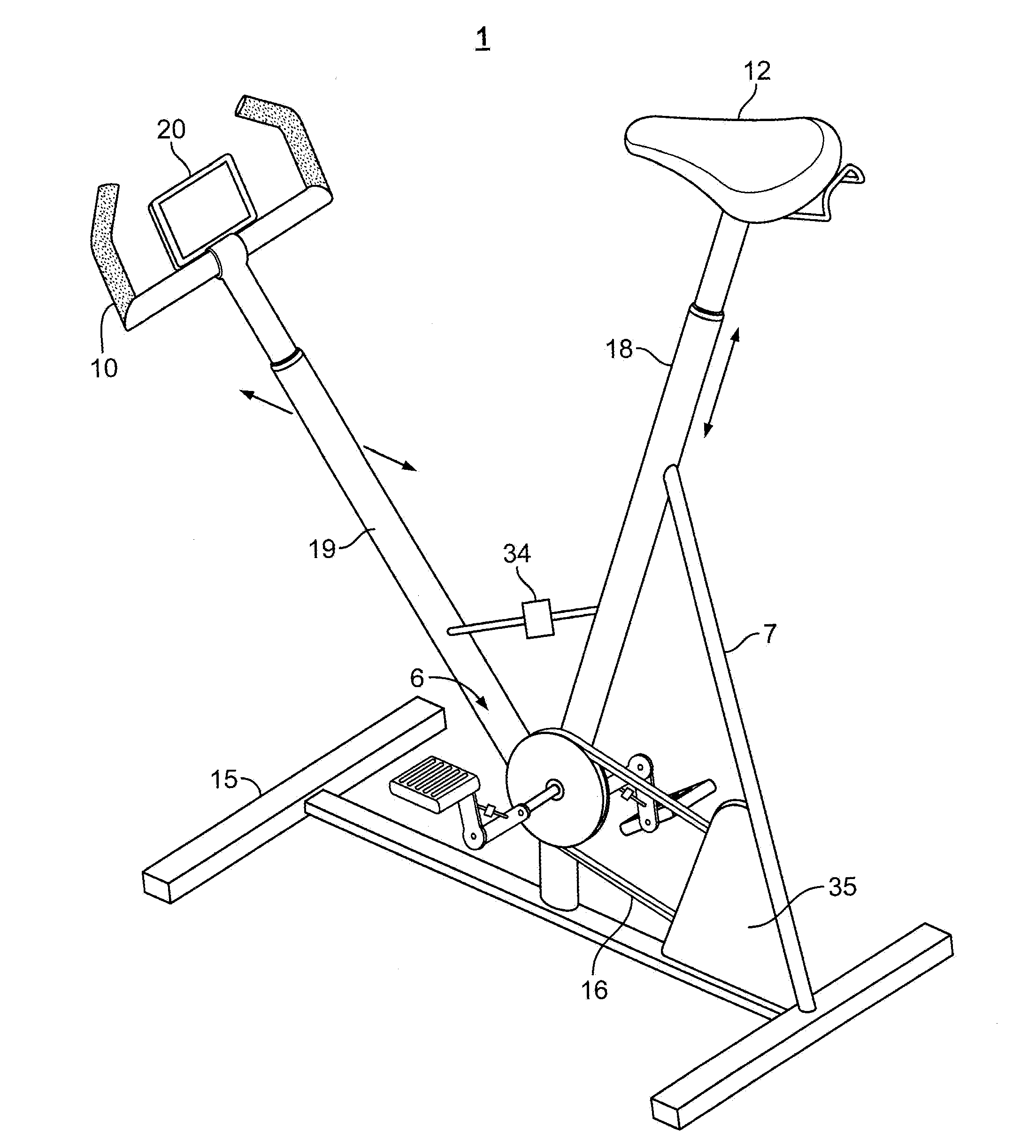
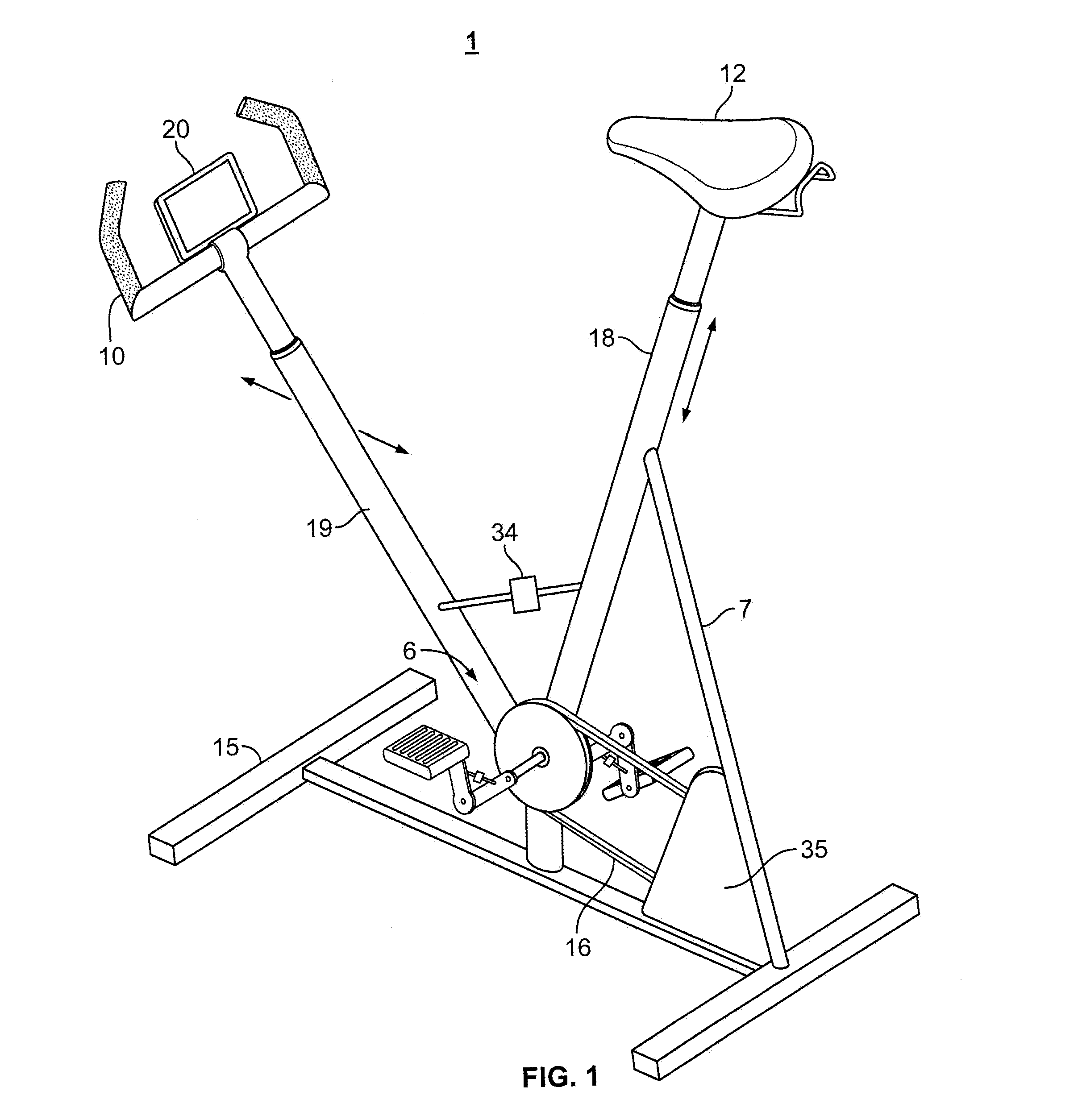
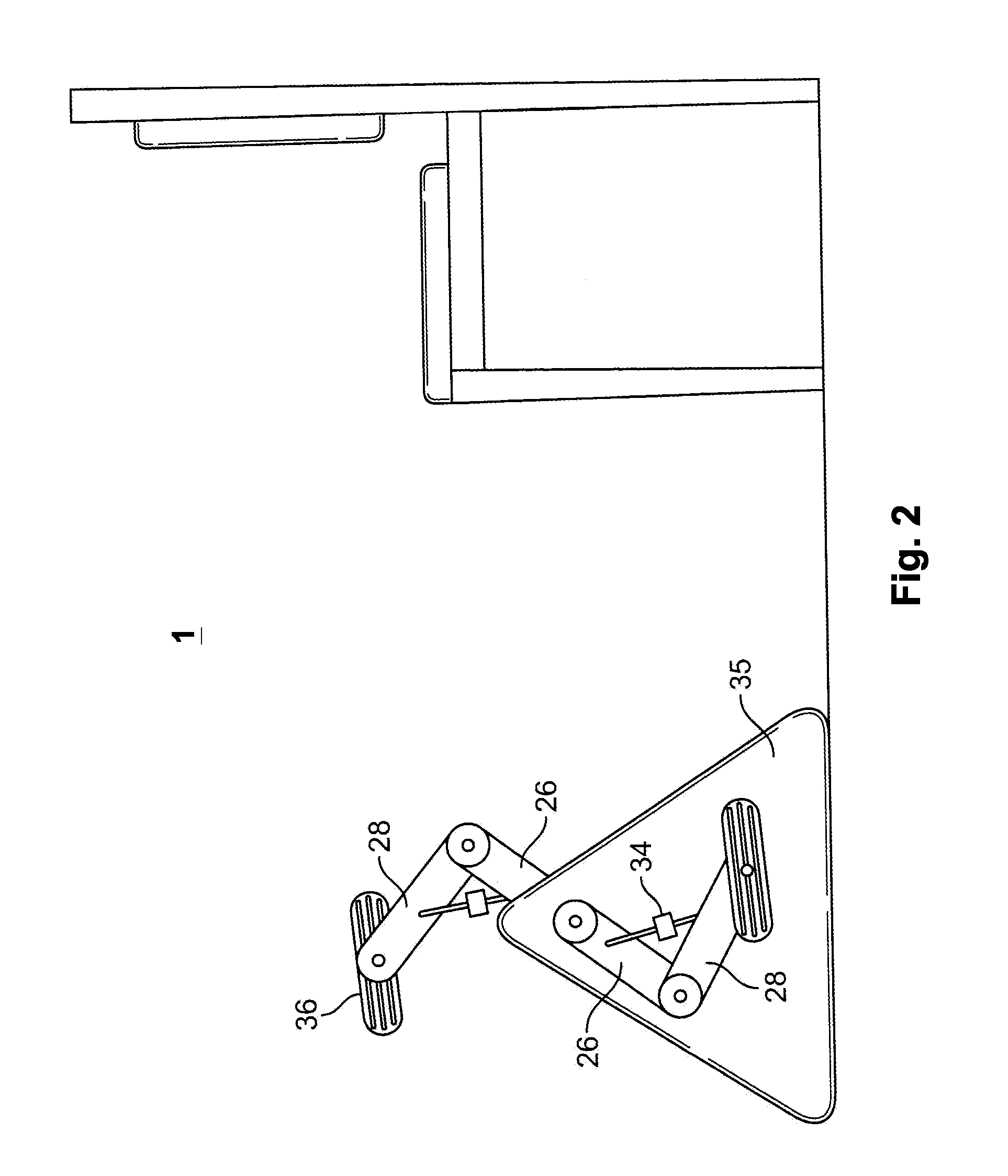
[0042]Referring to FIG. 1, there is a first embodiment of the present invention. The rehabilitation device 1 has a first vertical support 19 and a second vertical support 18. The second vertical support 18 is further supported by a rear support 7. The first vertical support 19 has a pivoting joint 6. The pivoting j...


PUM


Abstract

A device for joint rehabilitation after injury or surgery and a method of use are described and taught. The device automatically senses and manipulates performance parameters to optimize the rehabilitation process in response to user performance. In particular, device sets the pedal throw and other variables automatically to be in an optimum range for the patient based on the respective patient data. A motor resistance unit allows for the user to experience variable resistances while using the device. This not only increases the patient's range of motion but also strengthens and increases muscle tone. In order to use the device, the patient or user simply inputs preliminary parameters and the on-board computer then calculates a rehabilitation plan, and monitors patient performance and adapts to changes. The central data server permit central storage of all data associated with usage of the rehab devices and is fully HIPAA compliant.

Description

CLAIM OF PRIORITY[0001]This application claims priority to U.S. Provisional Application 61 / 776,904 filed on Mar. 12, 2013 the contents of which are herein incorporated by reference in their entirety.FIELD OF THE INVENTION[0002]The field of the invention relates to rehabilitation devices, namely devices that help people recover from joint injuries, surgeries or the like. In particular, to equipment with pedals or linear sleds, which are used by therapists, to help increase flexibility, strength, and muscle tone by repeatedly taking the injured appendage through a range of motion.BACKGROUND OF THE INVENTION[0003]Bicycles were first introduced in early-mid 19th century Europe. Today, there are twice as many bicycles as there are cars. Bicycles are human-powered modes of transportation typically consisting of a frame, two wheels, seat, handlebars, pedals, gears, and a chain. By using the pedals, one can propel the bicycle forward and can control the speed at which they move by varying t...

Claims


Application Information

Patent Timeline
IPC IPC(8): A63B24/00A63B23/04
CPCA63B23/0476A63B24/0087A63B21/0058A63B22/0605A63B22/0694A63B24/0062A63B71/0619A63B2024/0065A63B2024/0068A63B2024/0093A63B2220/30A63B2220/833A63B2225/096A63B2225/50A63B21/4033
Inventor BOYETTE, ROBERT B.KOLB, MARK E.
Owner BOYETTE ROBERT B
Learn More