Zero reflux female valve with small priming volume

a technology of reflux female valve and priming volume, which is applied in the direction of valves, intravenous devices, infusion devices, etc., can solve the problems of undesirable retention of medical fluid within the connector, large size of certain conventional needleless self-sealing connectors, and significant axial force on the valve element. , to achieve the effect of reducing the amount of fluid and reducing the siz

Active Publication Date: 2014-09-18
CAREFUSION 303 INC
View PDF3 Cites 26 Cited by
  • Summary
  • Abstract
  • Description
  • Claims
  • Application Information

AI Technical Summary

Benefits of technology

[0006]In accordance with certain embodiments, a needleless connector may be self-sealing and include a female Luer connector for engagement with a medical implement. The needleless connector may be reduced in size compared to conventional connectors and, therefore, a reduced amount of fluid may be trapped, if any, within the needleless connector upon disconnection of the medical implement. The connector also accepts a standard male Luer fitting and provides a self-sealing port with a continuous external surface at the port when the connector is not activated such that the port may be disinfected prior to or after use.

Problems solved by technology

For example, certain conventional needleless self-sealing connectors are relatively large and require a significant axial force on the valve element to activate the connector.
This axial force may cause stress on a fused connection of the housing that houses the valve element.
As certain types of medical fluids may degrade within a treatment time period, retention of medical fluid within the connector is undesirable and may be exacerbated with larger conventional connectors.
For example, build-up of certain medical fluids may cause occlusions that may impair the functionality of the connector and / or hazardously release such occlusions into the IV set.

Method used


Image

  • Zero reflux female valve with small priming volume
  • Zero reflux female valve with small priming volume
  • Zero reflux female valve with small priming volume

Examples


Embodiment Construction

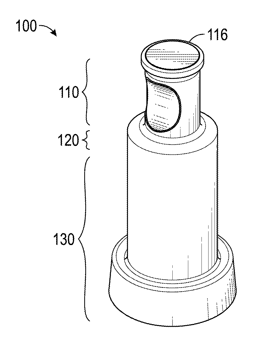
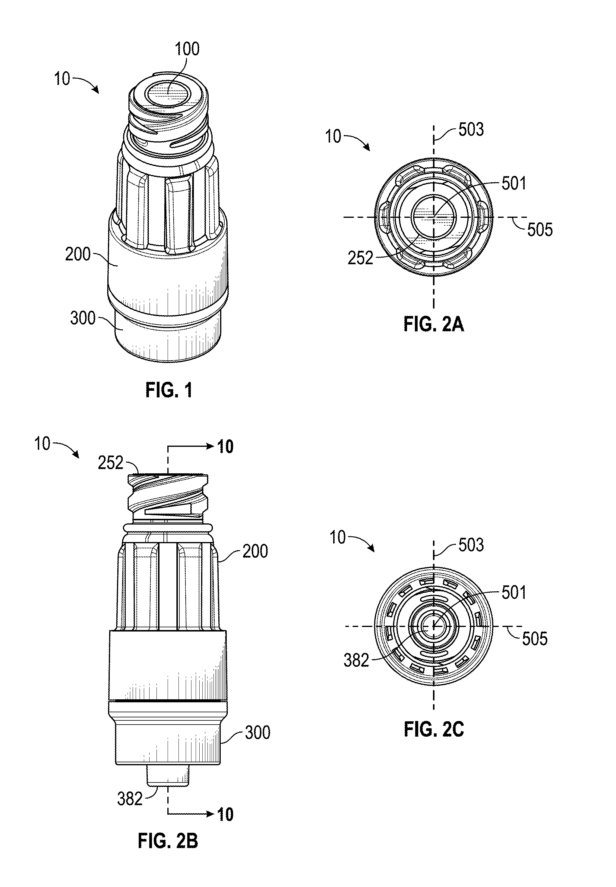
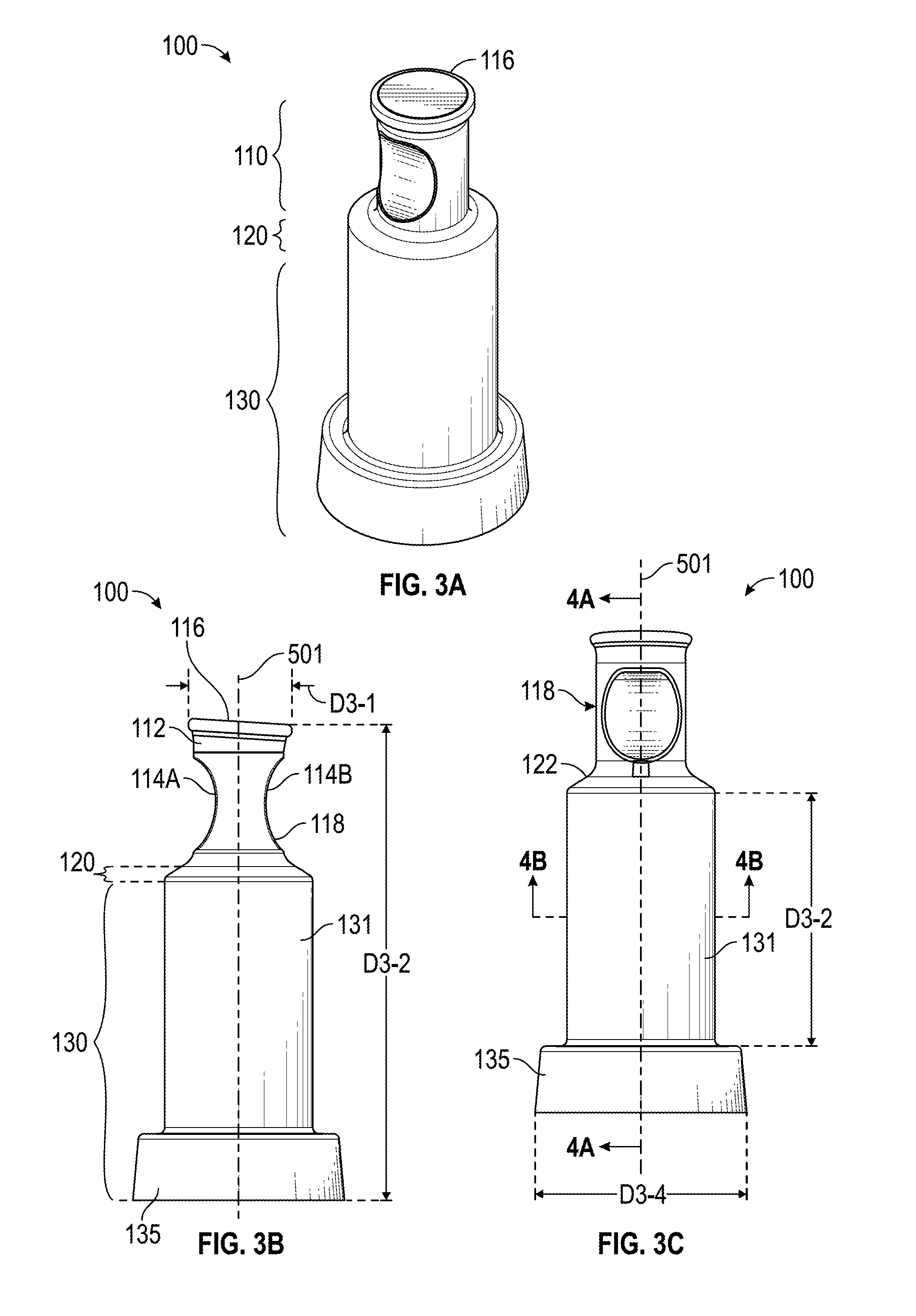
[0050]The detailed description set forth below describes various configurations of the subject technology and is not intended to represent the only configurations in which the subject technology may be practiced. The detailed description includes specific details for the purpose of providing a thorough understanding of the subject technology. Accordingly, dimensions are provided in regard to certain aspects as non-limiting examples. However, it will be apparent to those skilled in the art that the subject technology may be practiced without these specific details. In some instances, well-known structures and components are shown in block diagram form in order to avoid obscuring the concepts of the subject technology. Like components are labeled with identical element numbers for ease of understanding. Reference numbers may have letter suffixes appended to indicate separate instances of a common element while being referred to generically by the same number without a suffix letter.

[0...


PUM


Abstract

Needleless connectors are described. An example needleless connector includes a housing and a compressible valve. The housing may define an internal cavity and may include a body section having a first port and one or more internal contact tabs and a base section having a valve mount and a second port. The compressible valve may be disposed within at least a portion of the internal cavity and be movably retained within the housing. The compressible valve may include a flange portion for securing the compressible valve within the housing. A central longitudinal axis of the housing may be defined by a coaxial arrangement of the first and second port. The one or more internal contact tabs may be arranged to contact an outer side surface of the flange portion such that a radial force substantially orthogonal to the central longitudinal axis is provided for securement.

Description

CROSS-REFERENCES TO RELATED APPLICATIONS[0001]The present application is a continuation-in-part and claims the benefit of U.S. patent application Ser. No. 13 / 801,399, entitled “COLLAPSIBLE VALVE WITH INTERNAL DIMPLES,” filed on Mar. 13, 2013, is a continuation-in-part and claims the benefit of U.S. patent application Ser. No. 13 / 801,412, entitled “NEEDLELESS CONNECTOR WITH FOLDING VALVE,” filed on Mar. 13, 2013, is a continuation-in-part and claims the benefit of U.S. patent application Ser. No. 13 / 829,227, entitled “NEEDLELESS CONNECTOR WITH FLEXIBLE VALVE,” filed on Mar. 14, 2013, is a continuation-in-part and claims the benefit of U.S. patent application Ser. No. 13 / 829,187, entitled “NEEDLELESS CONNECTOR WITH SUPPORT MEMBER,” filed on Mar. 14, 2013, and is a continuation-in-part and claims the benefit of U.S. patent application Ser. No. 13 / 801,422, entitled “NEEDLELESS CONNECTOR WITH REDUCED TRAPPED VOLUME,” filed on Mar. 13, 2013, each of which is hereby incorporated by referen...

Claims


Application Information

Patent Timeline
Patent Type & Authority Applications(United States)
IPC IPC(8): A61M39/26A61M39/10
CPCA61M39/26A61M39/10A61M39/22A61M39/24A61M2039/2433
Inventor MANSOUR, GEORGE MICHELZOLLINGER, CHRISTOPHER J.QUACH, MATTHEWYEH, JONATHAN
Owner CAREFUSION 303 INC
Why Eureka
Try Eureka