Eureka AIR delivers breakthrough ideas for toughest innovation challenges, trusted by R&D personnel around the world.

Spiral vena cava filter removal device

Inactive Publication Date: 2014-09-18
COOK MEDICAL TECH LLC
View PDF3 Cites 4 Cited by
  • Summary
  • Abstract
  • Description
  • Claims
  • Application Information

AI Technical Summary

Benefits of technology

The present invention provides an intravascular filter removal device that can be used to retrieval a filter from a patient's vena cava. The device includes an outer sheath, a first inner sheath, and a retrieval coil. The retrieval coil is designed to grasp the filter and can be made of Nitinol or magnetic. The device can easily be positioned and deployed to remove the filter from the patient's vena cava. The method of removing the filter involves inserting the outer sheath, positioning the retrieval coil over the inner sheath, extending the retrieval coil to securely coil around the filter, and then retracting the entire apparatus. The technical effect of this invention is to provide a simple and effective way to remove filters from a patient's vena cava.

Problems solved by technology

Patients having such medical conditions face an increased risk of thrombosis in the peripheral vasculature, wherein thrombi break away from the vessel wall, risking downstream embolism or embolization.
For example, depending on the size, such thrombi pose a serious risk of pulmonary embolism wherein blood clots migrate from the peripheral vasculature through the heart and into the lungs.
A particular problem that can arise during deployment of the filter or during treatment is misalignment of the filter.
Removal can be hindered or rendered impossible by minimally invasive means if the filter has become tilted during treatment.
A practitioner may not be able to snare the hook of a tilted filter because some portion of the hook may have made contact with the vessel wall, and in some cases the vessel may have grown around it.
Development of a device with the purpose of removing a tilted vena cava filter has proven difficult.

Method used


Image

  • Spiral vena cava filter removal device
  • Spiral vena cava filter removal device
  • Spiral vena cava filter removal device

Examples


Embodiment Construction

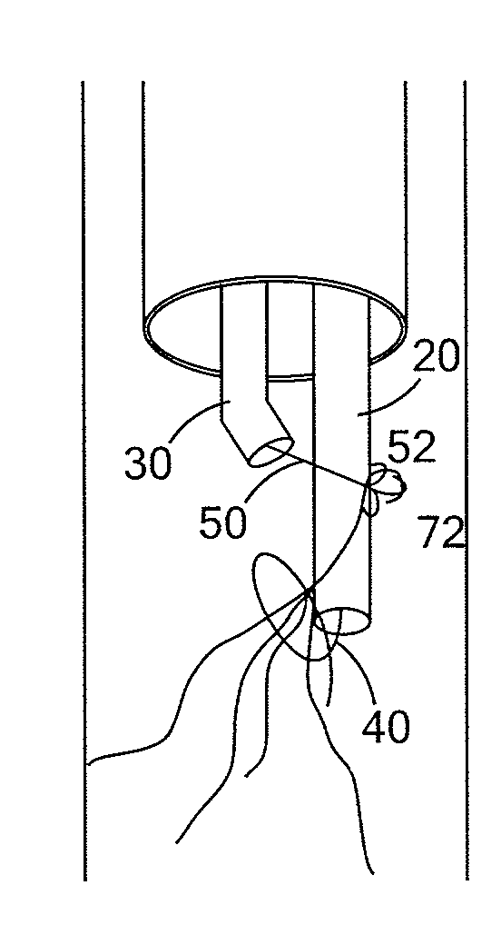
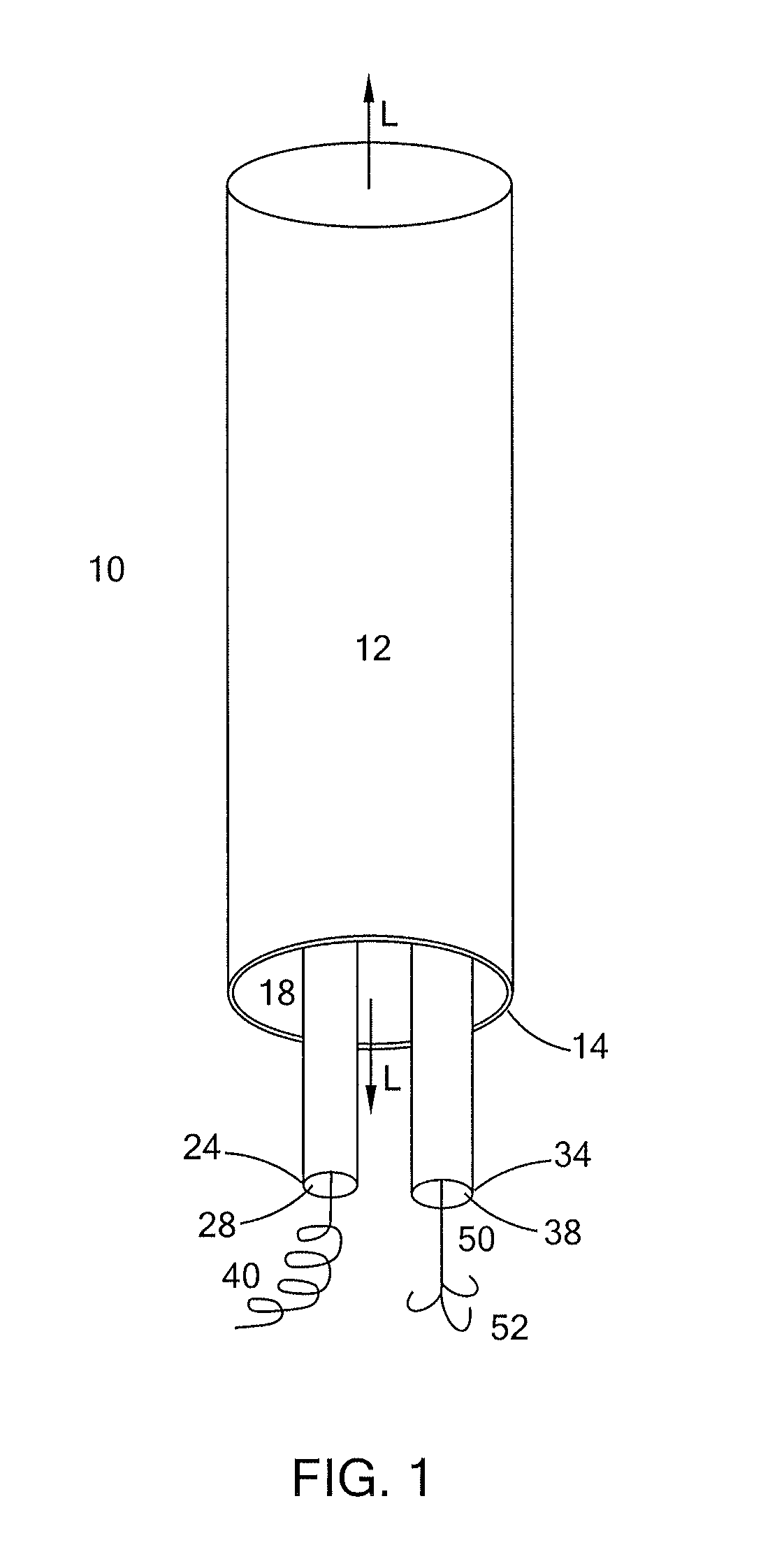
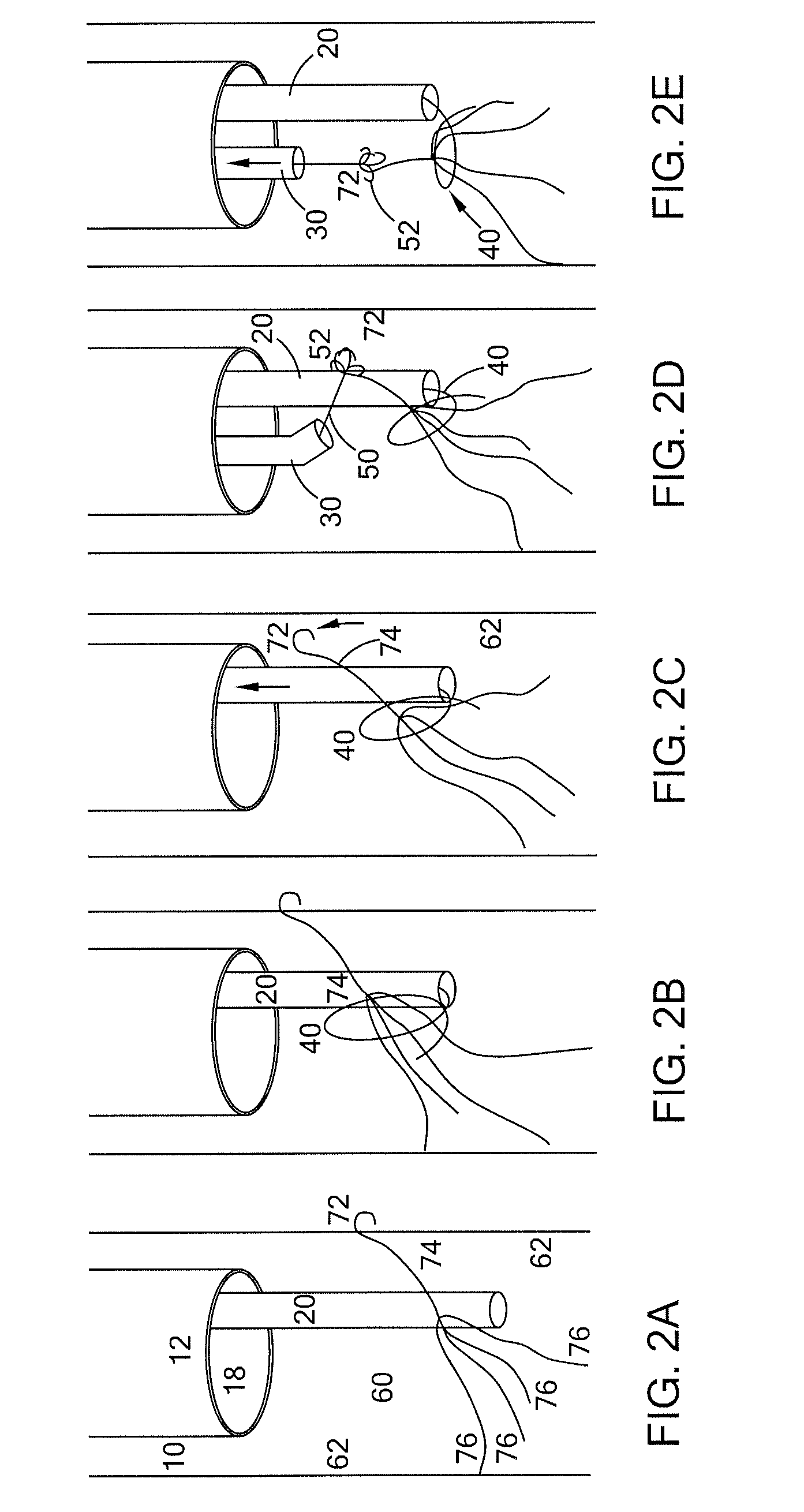
[0016]Provided herein is a device for removal of an intravascular filtration device that has been deployed in the vasculature of a patient. The filtration device is generally implanted in order to capture blood clots that may have formed so that they do not travel into portions of the body where their presence may cause damage. Most blood clots form in the lower limbs and are especially problematic if they reach the heart or lungs. As such, many filters are placed in the inferior vena cava, as this vein returns blood from the lower extremities to the heart. However, the device as described can also be used to extract filters from other veins as well.

[0017]The type of filters envisioned for removal by this device are roughly cone- or tulip-shaped filters which comprise a plurality of struts that diverge from an apical hub and are configured to engage the vessel wall at their opposite ends. These ends may terminate in hooks or barbs to more firmly engage the vessel wall. The filters a...


PUM


Abstract

A retrieval device for removing filter devices from body cavities is provided. The retrieval device comprises at least an outer sheath, a first inner sheath, and a retrieval coil configured to coil around the outer surface of a filter device to initiate retraction. In a preferred embodiment, a second inner sheath is also provided. The two inner sheaths are configured to be slideable within the outer sheath. The second inner sheath contains a snaring wire. The snaring wire and the retrieval coil collaborate to dislodge a filter device from the vasculature, then the entire assembly is retracted and withdrawn. Particularly, the combined actions of the snaring wire and the retrieval coil facilitate the removal of filter devices that have become tilted or misaligned during deployment or treatment.

Description

CROSS-REFERENCE TO RELATED APPLICATIONS[0001]This application claims the benefit of U.S. Provisional Application No. 61 / 783,307 filed on Mar. 14, 2013, entitled “SPIRAL TILTED VENA CAVA FILTER REMOVAL,” the entire contents of which are incorporated herein by reference.BACKGROUND[0002]The present invention relates to medical devices. More particularly, the invention relates to an intravascular filter removal device that can be used to assist in the removal of a filter from the vena cava of a patient.[0003]Filtering devices that are percutaneously placed in the vena cava have been available for a number of years. A need for such filtering devices arises in trauma patients, orthopedic surgery patients, neurosurgery patients, or in patients having medical conditions requiring bed rest or non-movement. Patients having such medical conditions face an increased risk of thrombosis in the peripheral vasculature, wherein thrombi break away from the vessel wall, risking downstream embolism or ...

Claims


Application Information

Patent Timeline
IPC IPC(8): A61B17/50
CPCA61B17/50A61B2017/22035A61F2/011A61F2/0105
Inventor MANNING, SAMANTHA
Owner COOK MEDICAL TECH LLC
Why Eureka
Eureka Blog
Learn More