Puncture and abrasion resistant sheath

a technology of abrasion resistance and sheath, which is applied in the field of puncture and abrasion resistance sheath, can solve the problems of contacting and possibly damaging the blood vessel, abraded inner surface, and damage to the outer sheath, and achieve the effect of improving puncture and abrasion resistan

Inactive Publication Date: 2008-05-22
COOK INC
View PDF27 Cites 36 Cited by
  • Summary
  • Abstract
  • Description
  • Claims
  • Application Information

AI Technical Summary

Benefits of technology

[0007]In satisfying the above need, as well as overcoming the enumerated drawbacks and other limitations of the related art, the present invention provides a delivery apparatus for introducing an implant for capturing emboli in a body vessel. The apparatus includes an outer sheath having a tubular wall defining a lumen formed therethrough and having a proximal end extending to a distal end. The tubular wall may include optional reinforcing members. The tubular wall has an inner surface and may include a radiopaque marker band disposed adjacent the distal end. A tubular liner is disposed along the inner surface for improved puncture and abrasion resistance. The tubular liner comprises at least one of polyimide, polyetheretherketones (PEEK), and polyvinylidene fluoride (PVDF).

Problems solved by technology

Since the outer sheath is usually made of a soft, flexible material there is a potential for damage to the outer sheath caused by stiff or sharp portions of the implants.
Consequently, any sharp portions, such as hooks, of the implant may puncture the outer sheath, prematurely contacting and possibly damaging the blood vessel.
In addition, the sharp or stiff portions may also abrade the inner surface, potentially introducing particulate matter from the outer sheath into the blood vessel.

Method used


Image

  • Puncture and abrasion resistant sheath
  • Puncture and abrasion resistant sheath
  • Puncture and abrasion resistant sheath

Examples


Embodiment Construction

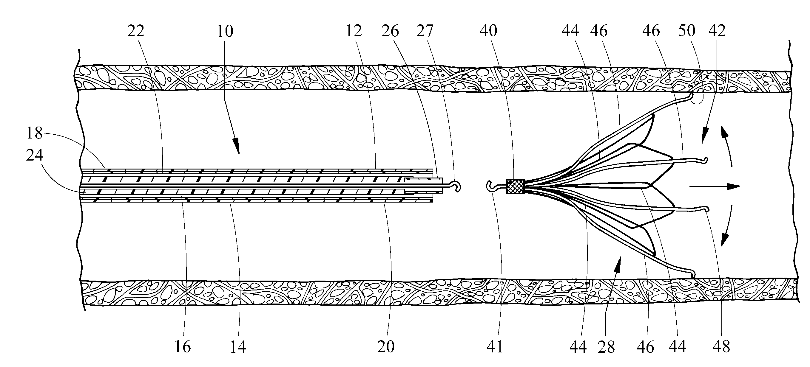
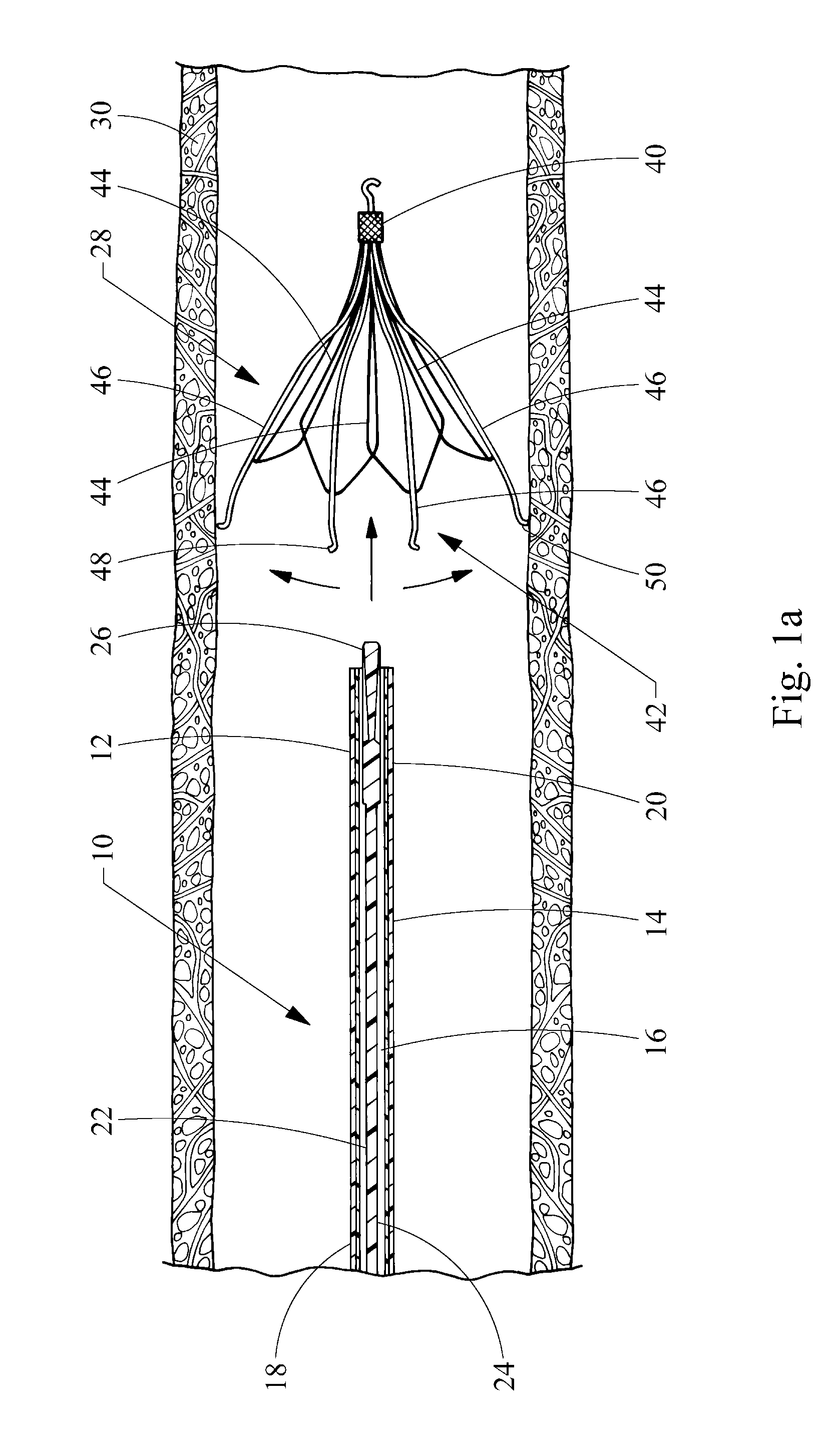
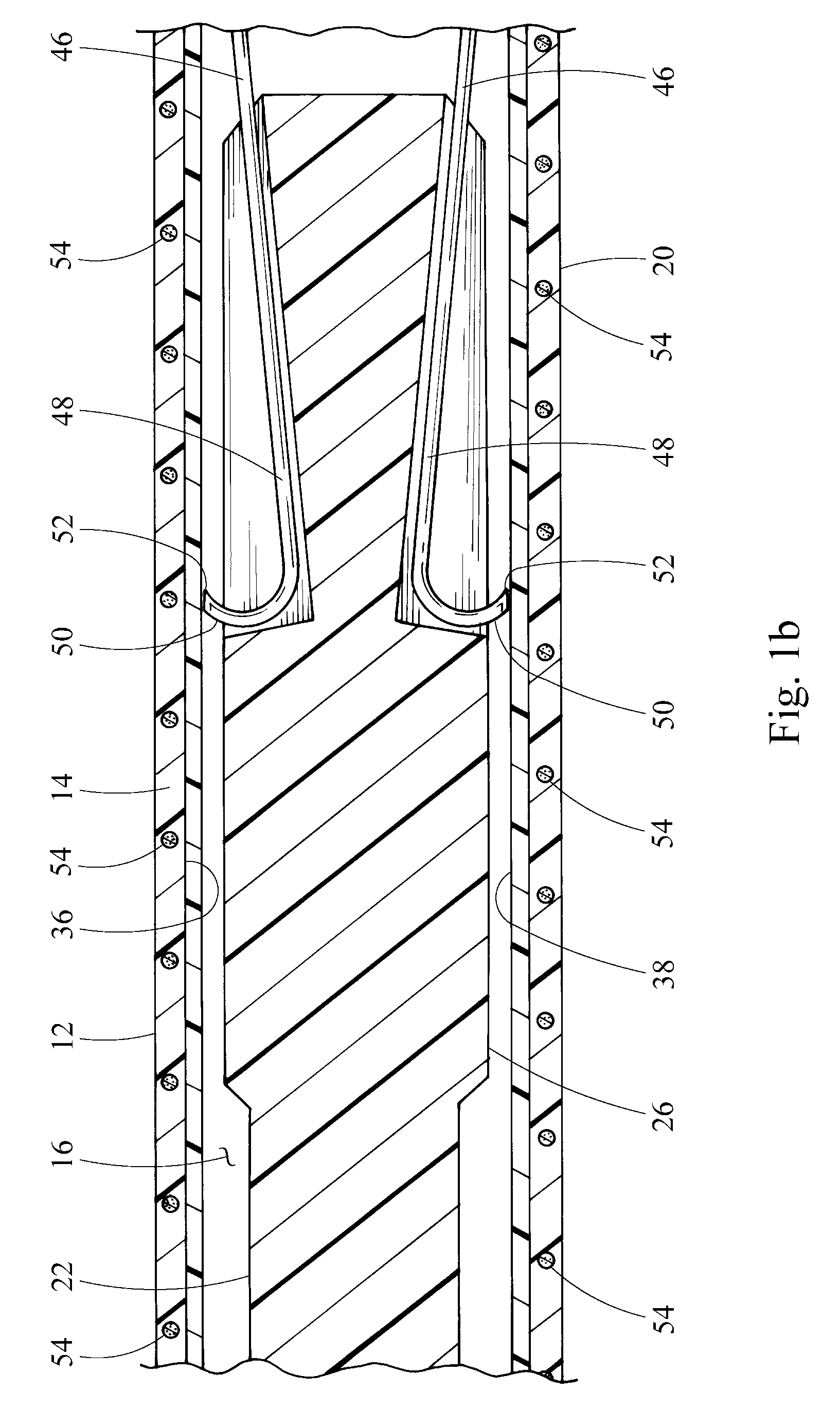
[0027]Referring now to FIG. 1a, a delivery apparatus embodying the principles of the present invention is illustrated therein and designated at 10. As its primary components, the apparatus 10 includes an outer sheath 12 having a proximal end 18 extending to a distal end 20 and a tubular wall 14 defining a lumen 16 formed therethrough. The apparatus 10 further includes an inner catheter 22 slidably disposed within the lumen 16 of the outer sheath 12. The inner catheter 22 has a proximal portion 24 extending to a distal portion 26 and is configured to longitudinally move relative to the outer sheath 12 and to engage and deliver an implant 28 through the distal end 20 of the outer sheath 12 into a body vessel 30.

[0028]FIG. 1a shows a vena cava filter, but the implant 28 may include any device appropriate for capturing emboli in the body vessel 30, or any other appropriate implant, such as a stent. The vena cava filter of FIG. 1a has a proximal segment 42 extending to distal segment 40....


PUM

PropertyMeasurementUnit
forceaaaaaaaaaa
densityaaaaaaaaaa
strengthaaaaaaaaaa

Abstract

A delivery apparatus for introducing an implant, such as a vena cava filter, for capturing emboli in a body vessel. The apparatus includes an outer sheath having a tubular wall defining a lumen formed therethrough and having a proximal end extending to a distal end. The tubular wall includes an inner surface and may also include optional reinforcing members. A radiopaque marker band is disposed about the inner surface adjacent the distal end, and a tubular liner is disposed along the inner surface. The tubular liner comprises at least one of polyimide, PEEK, and PVDF. An inner catheter is slidably disposed within the lumen of the outer sheath and has a distal portion configured to engage and deliver the implant through the distal end of the outer sheath in the body vessel.

Description

CROSS-REFERENCE TO RELATED APPLICATIONS[0001]This application claims the benefit of U.S. Provisional Application Ser. No. 60 / 855,497 filed on Oct. 31, 2006, entitled “PUNCTURE AND ABRASION RESISTANT SHEATH,” the entire contents of which are incorporated herein by reference.BACKGROUND[0002]1. Field of the Invention[0003]The present invention generally relates to delivery apparatus for vascular implants. More specifically, the invention relates to an introduction sheath having a protective liner for use with a vena cava filter.[0004]2. Description of Related Art[0005]Delivery apparatus for vascular implants include, for example, catheters having outer sheaths. An outer sheath must be conducive to navigating the tortuous bends found in blood vessels of the vascular system while also protecting the blood vessels from damage by the implants. Since the outer sheath is usually made of a soft, flexible material there is a potential for damage to the outer sheath caused by stiff or sharp por...

Claims


Application Information

Patent Timeline
Patent Type & Authority Applications(United States)
IPC IPC(8): A61M25/01
CPCA61F2/01A61F2002/011A61M25/0045A61F2230/008A61M2025/0681A61F2002/016A61F2230/005A61M25/005A61F2/011
Inventor DELANEY, KEVIN L.
Owner COOK INC
Why Eureka
Try Eureka