Dynamic tuning of a gas turbine engine to detect and prevent lean blowout

a gas turbine engine and dynamic tuning technology, applied in the direction of instruments, process and machine control, computer control, etc., can solve the problems of affecting and affecting the operation of the gas turbine engine. , to achieve the effect of changing the performance prolonging the down-time of the gas turbine engin

Active Publication Date: 2014-09-18
H2 IP UK LTD
View PDF14 Cites 11 Cited by
  • Summary
  • Abstract
  • Description
  • Claims
  • Application Information

AI Technical Summary

Benefits of technology

[0003]Increasingly, a control system is used to regulate the operation of the gas turbine engine. In operation, the control system receives a plurality of indications that communicate the current operating conditions of the gas turbine engine including pressures, temperatures, fuel-flow rates, and engine frequencies. In response, the control system makes adjustments to the inputs of the gas turbine engine, thereby changing performance of the gas turbine engine. Over time, this performance may fall outside a preferred operating range due to mechanical degradation of the gas turbine engine or changes in operational conditions such as ambient temperature or fuel constituents. For instance, the gas turbine engine may start operating beyond regulated emissions limits As such, multiple manual tunings are required to update the control system. Manual tuning can be labor intensive and can sometimes create business-related inefficiencies, such as extended down-time of the gas turbine engine and operator error in the course of tuning. In addition, because there are specific windows of time where manual tuning may not be available (e.g., high dynamics events), but where performing a tuning operation would be beneficial to protect against potential damage to hardware, automatically tuning during those windows will capture benefits that may be missed when manual tuning is employed in some instances. Nonetheless, manual tuning may still be desirable in some instances, and embodiments of the present invention may be utilized for either automatic or manual tuning.

Problems solved by technology

Over time, this performance may fall outside a preferred operating range due to mechanical degradation of the gas turbine engine or changes in operational conditions such as ambient temperature or fuel constituents.
Manual tuning can be labor intensive and can sometimes create business-related inefficiencies, such as extended down-time of the gas turbine engine and operator error in the course of tuning.

Method used


Image

  • Dynamic tuning of a gas turbine engine to detect and prevent lean blowout
  • Dynamic tuning of a gas turbine engine to detect and prevent lean blowout
  • Dynamic tuning of a gas turbine engine to detect and prevent lean blowout

Examples


Embodiment Construction

[0017]The subject matter of the present invention is described with specificity herein to meet statutory requirements. However, the description itself is not intended to limit the scope of this patent. Rather, the inventors have contemplated that the claimed subject matter might also be embodied in other ways, to include different components, combinations of components, steps, or combinations of steps similar to the ones described in this document, in conjunction with other present or future technologies.

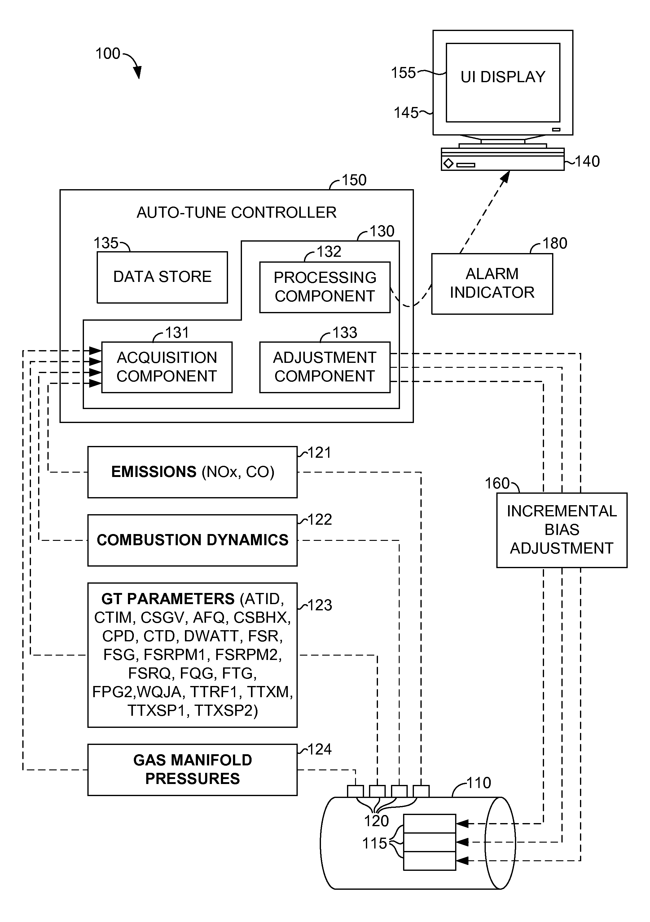
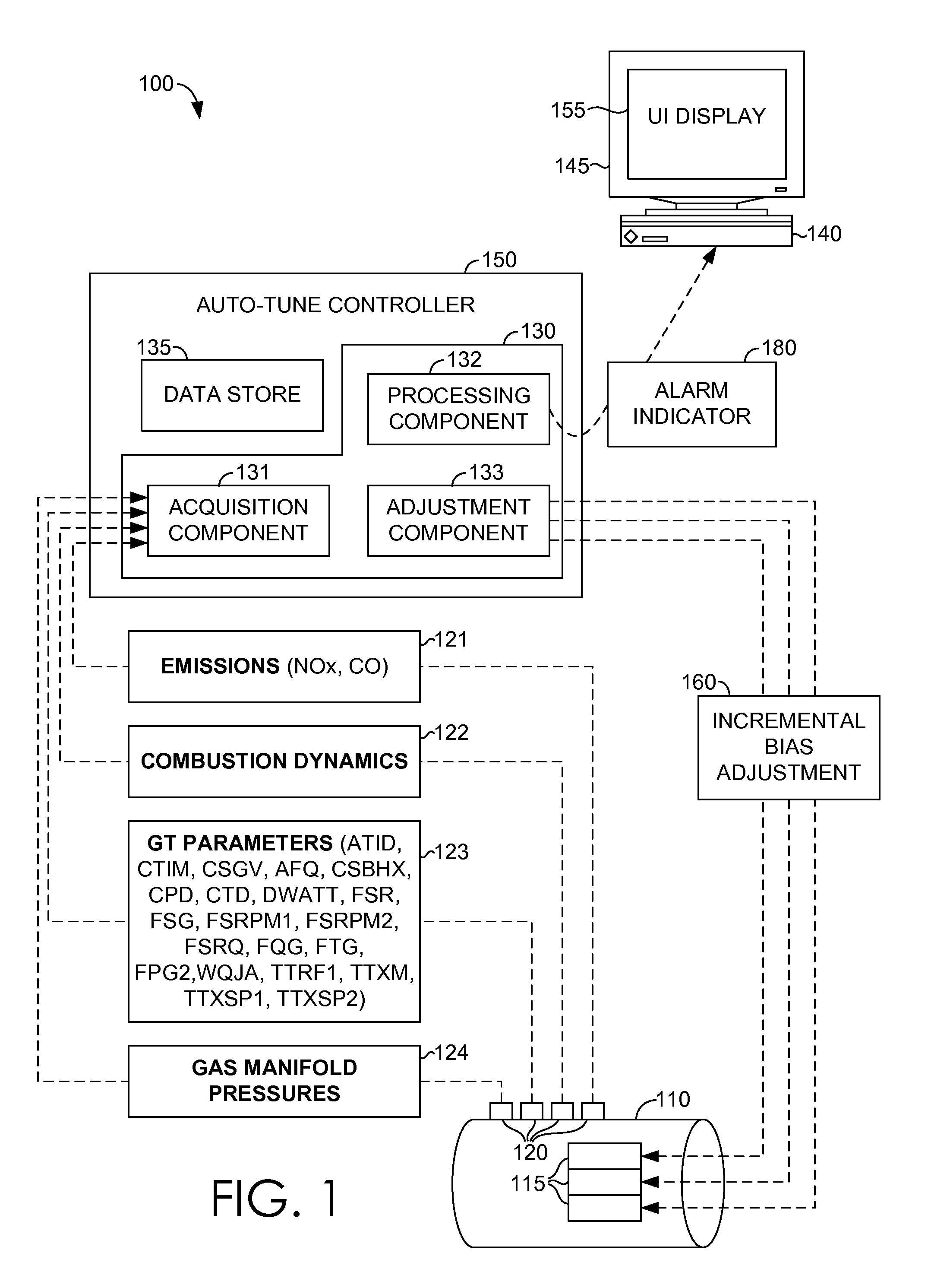
[0018]As described above, embodiments of the present invention generally relate to automatically tuning a gas turbine (GT) engine in a dynamic fashion. In some instances, tuning of staged GT combustion systems involves adjusting the applied fuel-flow split to ensure that dynamics and emissions are within specified limits As used herein, the phrase “fuel-flow split” refers to an instruction that governs a portion of a total fuel-flow that is directed to each fuel nozzle of a fuel cir...


PUM


Abstract

A method for tuning a combustor of a gas turbine engine based on one or more monitored operating conditions is provided. One or more operating conditions of the gas turbine engine are monitored. The monitored operating conditions may include, for example, a low frequency tone, a high frequency tone, and a ratio of the low frequency tone to the high frequency tone. It is determined whether the ratio of the low frequency tone to the high frequency tone is within a first predefined normal range. If the ratio of the low frequency tone to the high frequency tone is within the first predefined normal range, a determination is made not to tune the gas turbine engine. But, if the ratio of the low frequency tone to the high frequency tone is not within the first predefined normal range, a determination is made to tune the gas turbine engine.

Description

CROSS-REFERENCE TO RELATED APPLICATIONS[0001]This application claims priority to U.S. Provisional Application Ser. No. 61 / 790,161, filed Mar. 15, 2013, entitled “Dynamic Auto-Tuning of a Gas Turbine Engine,” which is incorporated herein in its entirety.BACKGROUND OF THE INVENTION[0002]Gas turbine engines operate to produce mechanical work or thrust. Specifically, land-based gas turbine engines typically have a generator coupled thereto for the purposes of generating electricity. The shaft of the gas turbine engine is coupled to the generator. Mechanical energy of the shaft is used to drive a generator to supply electricity to at least a power grid. The generator is in communication with one or more elements of a power grid through a main breaker. When the main breaker is closed, electrical current can flow from the generator to the power grid when there is a demand for the electricity. The drawing of electrical current from the generator causes a load to be applied to the gas turbin...

Claims


Application Information

Patent Timeline
Patent Type & Authority Applications(United States)
IPC IPC(8): G05B15/02
CPCG05B15/02F05D2260/964F02C9/00F02C9/22F02C9/48
Inventor STUTTAFORD, PETER JOHNSONI, SUMITGAUTHIER, DONALDRIZKALLA, HANY
Owner H2 IP UK LTD
Why Eureka
Try Eureka