Vehicle charging device

Inactive Publication Date: 2014-09-25
SUMITOMO WIRING SYST LTD
View PDF5 Cites 18 Cited by
  • Summary
  • Abstract
  • Description
  • Claims
  • Application Information

AI Technical Summary

Benefits of technology

[0015]According to the present invention, it is possible to detect the damage of a locking portion of an actuator c

Problems solved by technology

On the other hand, if the locking portion of the actuator is

Method used


Image

  • Vehicle charging device
  • Vehicle charging device
  • Vehicle charging device

Examples


Example

[0027]One embodiment of the present invention is described based on FIGS. 1 to 11.

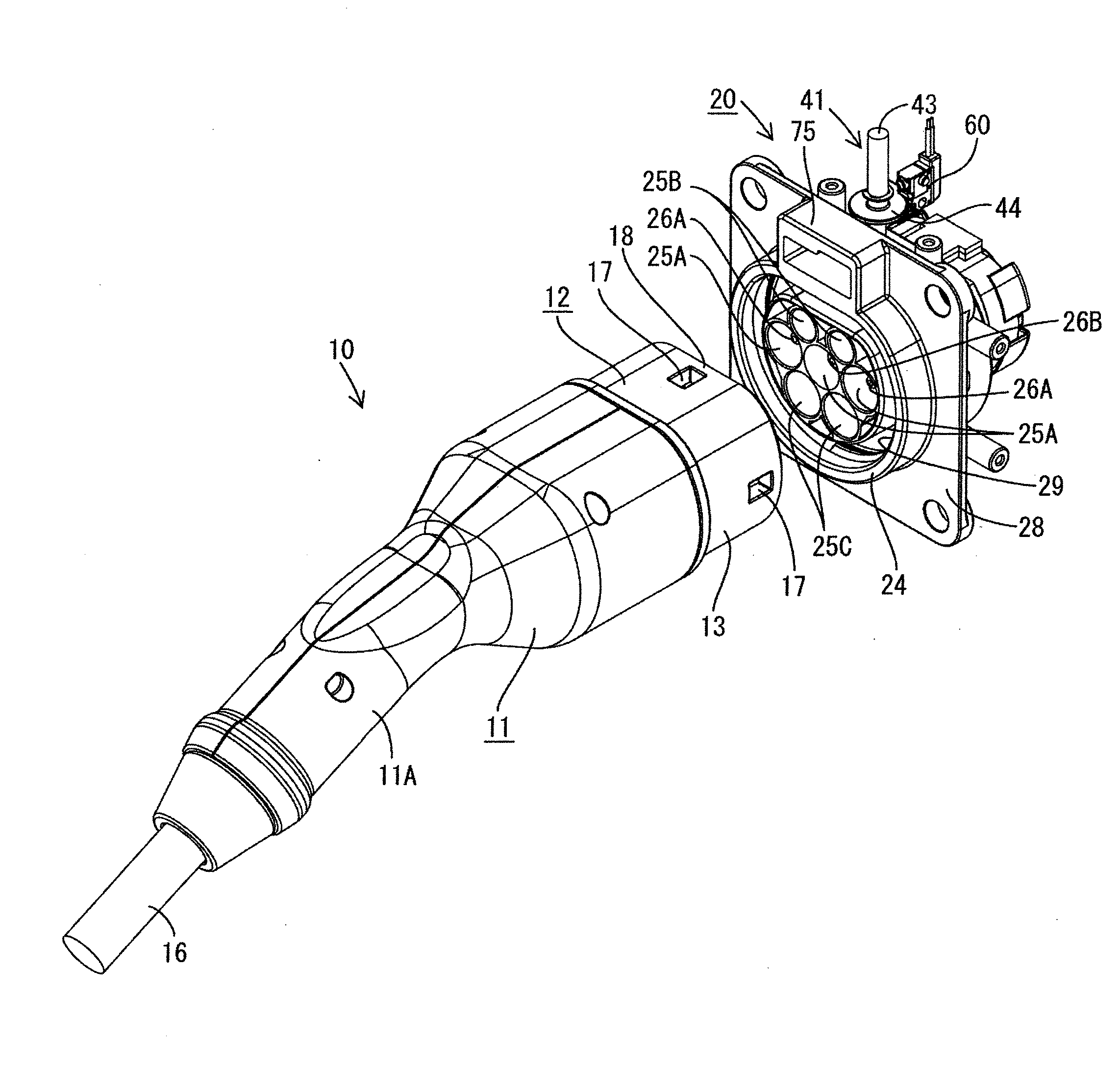
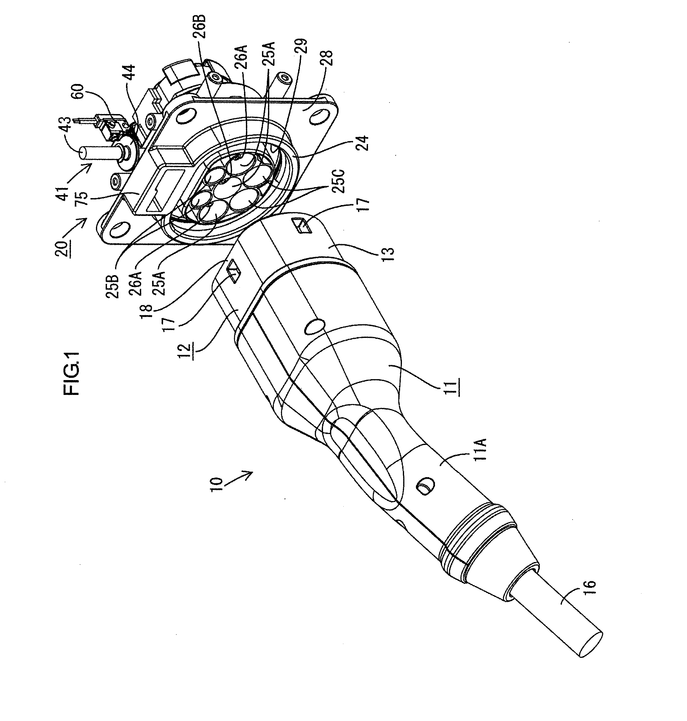
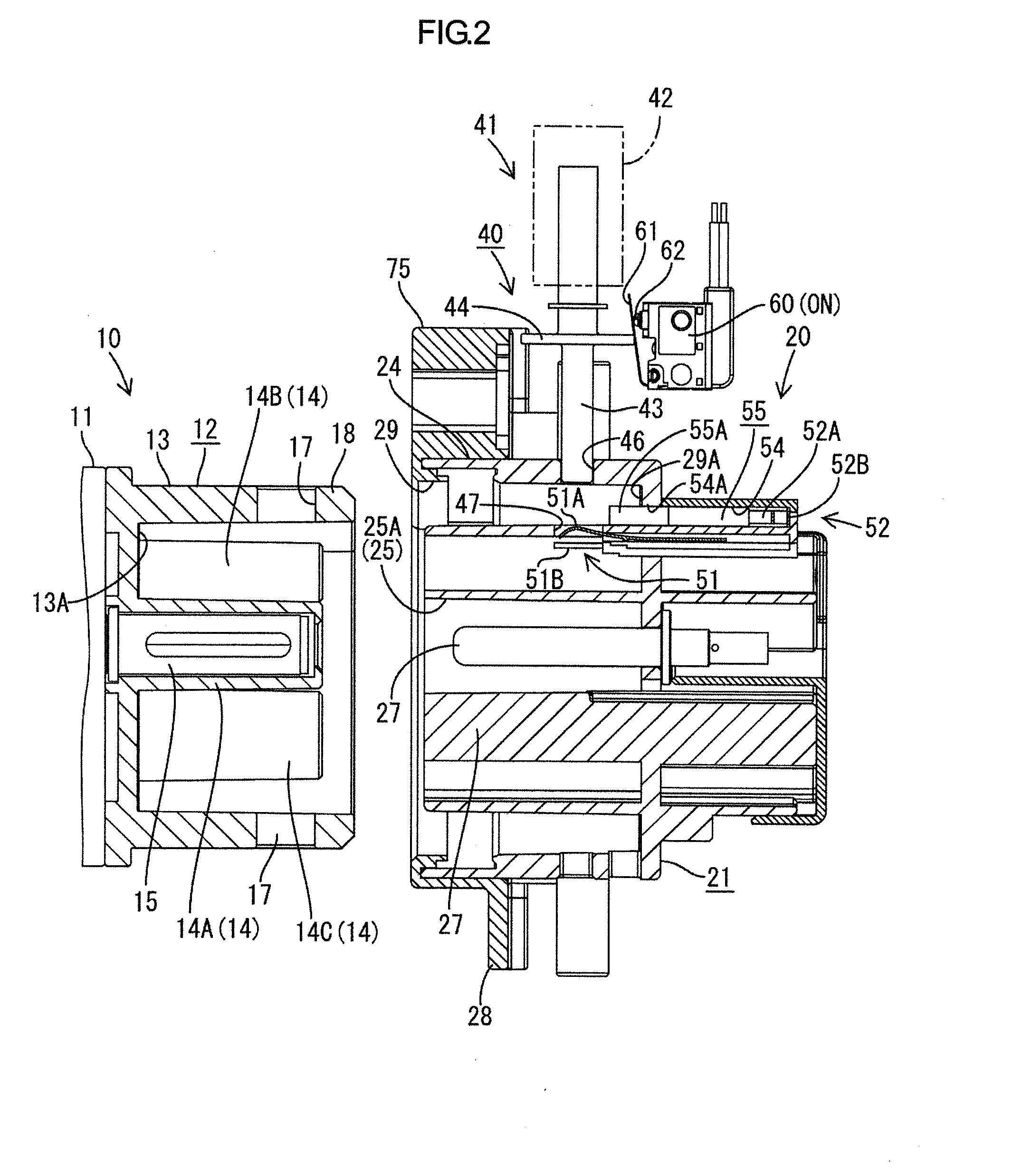
[0028]As shown in FIGS. 1 and 2, a vehicle charging device of this embodiment includes a power supply side connector 10 connected to a power supply and a vehicle side connector 20 connected to a battery mounted in a vehicle and provided in the vehicle.

[0029]The power supply side connector 10 is so structured that a female housing 12 is provided on a tip part of a connector main body 11 with a grip part 11A, both the connector main body 11 and the female housing 12 being made of synthetic resin. The female housing 12 is so structured that seven terminal accommodating tubes 14 independent of each other and projecting from the back wall are provided in a small receptacle 13 (corresponding to a receptacle of the present invention). Two, three and two terminal accommodating tubes 14 are respectively arranged in an upper row, a middle row and a lower row in correspondence with the arrangement of seven caviti...


PUM


Abstract

A vehicle charging device configured such that both connectors 10, 20 are locked in a connected state by an advancing movement of a locking portion 43 of an actuator 41 to be locked to a locked portion 18 when the connection of the both connectors 10, 20 is detected by a connection detector 31 includes a locking portion detector 51 for detecting whether or not the locking portion 43 of the actuator 41 has advanced to a predetermined locking position, and a power supply controller 71 for setting a power supply path to an electrically conductive state on a condition that an advancing movement of the locking portion 43 to the predetermined locking position is detected by the locking portion detector 51.

Description

BACKGROUND[0001]1. Field of the Invention[0002]The present invention relates to a vehicle charging device with an improved lock mechanism.[0003]2. Description of the Related Art[0004]In the case of charging a vehicle equipped with a battery such as an electric vehicle or a plug-in hybrid vehicle, a power supply side connector connected to a power supply is connected to a vehicle side connector provided in the vehicle and connected to the battery such as at home or at a gas station, whereby the battery is charged with power supplied from a commercial power supply. Since this charging requires a relatively long time, the both connectors are often left in a connected state. During that time, the power supply side connector may inadvertently come off such as because a power supply cord is tripped over or the power supply side connector may be unduly pulled out for the purpose of stealing electricity. Thus, measures for preventing these need to be taken.[0005]Conventionally, a charging d...

Claims


Application Information

Patent Timeline
IPC IPC(8): B60L11/18
CPCB60L11/1816H01R13/639H01R13/701B60L3/0069B60L3/04B60L2270/32B60L2270/34Y02T90/14B60L2250/10B60L53/14B60L53/16B60L53/305Y02T10/70Y02T10/7072Y02T90/12Y02T90/16
Inventor OSAWA, KIYOSHISHIMIZU, TOORUICHIO, TOSHIFUMI
Owner SUMITOMO WIRING SYST LTD
Why Eureka
Try Eureka