Eureka AIR delivers breakthrough ideas for toughest innovation challenges, trusted by R&D personnel around the world.

Multi-directional, multi-functional, wearable safety lighting apparatus

a safety lighting and multi-functional technology, applied in the direction of identification means, light source combinations, instruments, etc., can solve the problems of inability to readily access these features, inability to wear reflective clothing in covert situations, and often encountered safety issues of personnel and workers in transportation or power industries, so as to improve visibility and enhance user experien

Active Publication Date: 2014-09-25
ARCHANGEL DEVICE LLC
View PDF17 Cites 21 Cited by
  • Summary
  • Abstract
  • Description
  • Claims
  • Application Information

AI Technical Summary

Benefits of technology

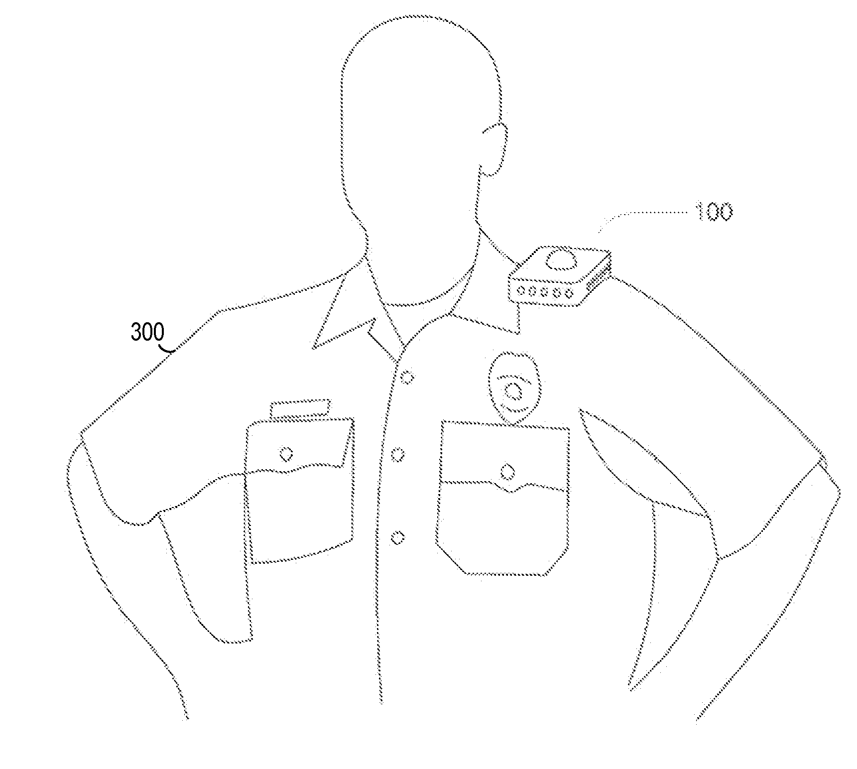
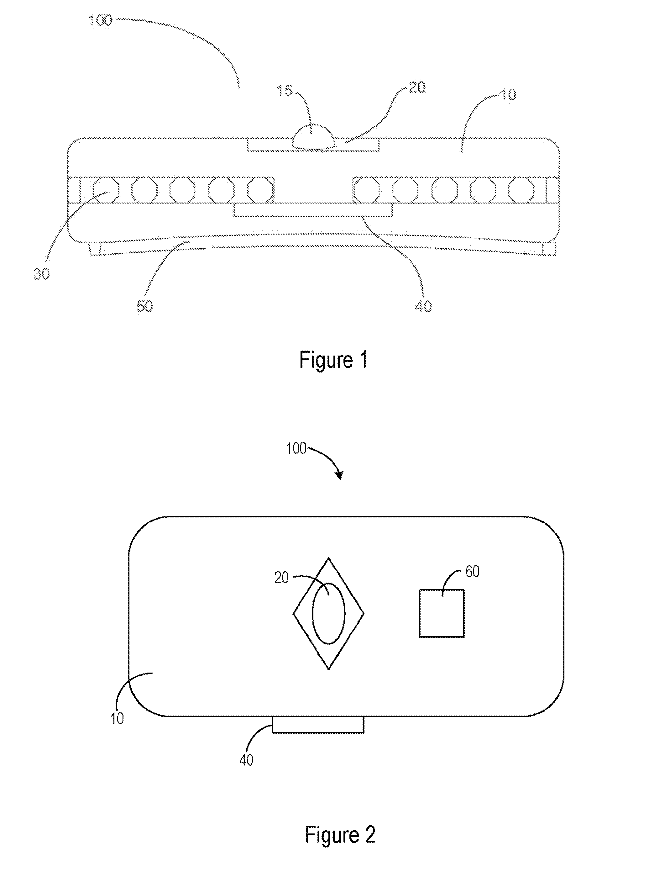
The invention is a portable and wearable device designed to increase safety and visibility for safety personnel when they leave their vehicles. It can be securely attached to the wearer and emits different visual and audio signals depending on what the user activates on a control panel. The device also has GPS capability for tracking, activizing, and deactivating functions. Overall, this invention helps to keep safety personnel safer and more easily visible when they leave their vehicles.

Problems solved by technology

Once an individual has left their vehicle, however, they may be unable to readily access these features.
Construction personnel and workers in the transportation or power industries frequently encounter similar safety issues when operating in their day-to-day jobs.
Wearing such reflective clothing may prove a hindrance to law enforcement or military personal in covert situations.
Also, these devices provide limited or no added visability during daylight hours in highly populated areas or in crowd control situations.
These devices also do not permit the user to be identified or located from a distance.
Further, in the case of flashlight-type devices, the device may serve to hinder the user in an emergency situation and slow the user in performing work-related tasks, since the device occupies one of the user's hands when in use.

Method used


Image

  • Multi-directional, multi-functional, wearable safety lighting apparatus
  • Multi-directional, multi-functional, wearable safety lighting apparatus
  • Multi-directional, multi-functional, wearable safety lighting apparatus

Examples


Embodiment Construction

[0033]For the purpose of promoting an understanding of the present invention, references are made in the text hereof to embodiments of a personal security alert device for safety personnel, only some of which are described herein. It should nevertheless be understood that no limitations on the scope of the invention are thereby intended. One of ordinary skill in the art will readily appreciate that modifications, such as the dimensions of a personal security alert device for safety personnel and use of alternate but functionally similar material(s), may be made. The inclusion of additional elements may be deemed readily apparent and obvious to one of ordinary skill in the art, and all equivalent relationships to those described in the written description do not depart from the spirit and scope of the present invention. Some of these possible modifications are mentioned in the following description. Therefore, specific details disclosed herein are not to be interpreted as limiting, b...


PUM


Abstract

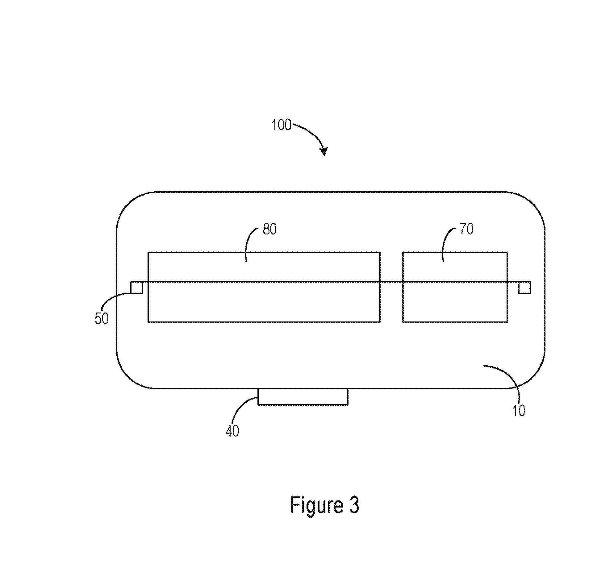
A multi-functional, multi-directional wearable safety lighting device is disclosed herein that includes a main light housing and a magnetic mounting assembly coupleable to a bottom surface of the main light housing. The mounting assembly is configured to secure the wearable safety lighting device to a user. The main light housing includes warning light elements coupled front and rear side surfaces. A directional work light is coupled to the front side surface of the main housing and is distinct from the warning light elements. A power source supplies power to the warning light elements and the work light. A controller is programmed to energize the warning light elements in select subgroups following depression of a first control button or a second control button, and energize the directional work light following depression of a third control button.

Description

CROSS-REFERENCE TO RELATED APPLICATIONS[0001]The present application is a continuation-in-part of and claims priority to U.S. application Ser. No. 13 / 676,549 filed on Nov. 14, 2012, which is a continuation of and claims priority to U.S. application Ser. No. 12 / 612,632 filed on Nov. 4, 2009, which is a non-provisional of and claims priority to U.S. Provisional Application No. 61 / 113,117 filed on Nov. 10, 2008, the disclosures of which are incorporated herein by reference.FIELD OF INVENTION[0002]The present invention relates generally to the field of safety and warning indicators and specifically to multifunctional beaconing devices for safety personnel.BACKGROUND[0003]Safety personnel such as law enforcement officers, firefighters, medical personnel, military personnel, and security personnel are frequently involved in situations where they must leave their vehicle or where they interact directly with crowds and the public. The vehicles used by safety personnel are generally equipped...

Claims


Application Information

Patent Timeline
IPC IPC(8): G08B5/36H05B44/00
CPCG08B5/36G08B5/004F21V23/003Y02E60/10H05B45/10F21Y2113/13F21Y2115/10F21L4/08F21V3/049F21V21/0965F21V23/0414F21V31/005F21V33/0076F21W2111/10G08B21/02H01M10/0525H01M10/46
Inventor MATTE, KEVIN D.DIR, RONALD R.STILLMAN, CHAD J.
Owner ARCHANGEL DEVICE LLC
Why Eureka
Eureka Blog
Learn More