Fluid transport apparatus

a technology of transport apparatus and fluid, which is applied in the field of apparatus, can solve the problems of limiting the predicted mechanical life of the heart pump, increasing the use of mechanical device therapy for heart failure treatment, and limiting the number of donor organs for heart transplantation. the effect of reducing the blood flow through the heart pump and increasing the blood flow through the pump

Inactive Publication Date: 2014-09-25
TIMMS DANIEL +2
View PDF0 Cites 24 Cited by
  • Summary
  • Abstract
  • Description
  • Claims
  • Application Information

AI Technical Summary

Benefits of technology

[0063]Typically at least part of an inlet compliant section moves between an expanded state under conditions of normal inlet pressure and a restricted state under conditions of reduced inlet pressure, thereby reducing blood flow through the heart pump as the inlet pressure decreases.
[0064]Typically at least part of an outlet compliant section moves between a restricted state under conditions of normal outlet pressure and an expanded state under conditions of increased outlet pressure, thereby increasing blood flow through the pump as the outlet pressure increases.

Problems solved by technology

The use of mechanical device therapy to treat heart failure is increasing as the general population ages and the number of donor organs for heart transplantation remains limited.
First generation pulsatile devices necessitate contacting components, which limits their predicted mechanical lifetime below three years.
However, initial techniques for impeller support also imposed significant limitations on device lifetime, as they required a shaft, seals and bearings U.S. Pat. No. 4,589,822.
Subsequent improvements resulted in devices that rely on blood immersed pivot support U.S. Pat. No. 5,601,418; however, predicted service life is still below five years.
However, this technique introduces an additional blood contacting conduit, as well as complexities involved with active feedback control, such as the need for sensors.
Furthermore, this solution can help to balance the fluid distribution but does not provide a method for controlling the alteration of device outflow.
This method of control may inherently consume excessive amounts of electrical power.
These components increase the possibility of device failure; as such components have limited long term reliability.
Furthermore, their addition to the device can induce extra blood contact with other foreign material, exacerbating the potential for blood damage.
A further issue is that active control systems reliant on sensors are prone to drift or use inferred data which may be inaccurate under certain situations such as partial / full inflow occlusion.
This in turn can render the pump ineffective in some scenarios.

Method used


Image

  • Fluid transport apparatus
  • Fluid transport apparatus
  • Fluid transport apparatus

Examples


Embodiment Construction

[0195]A first example of a heart pump will now be described with reference to FIG. 1A.

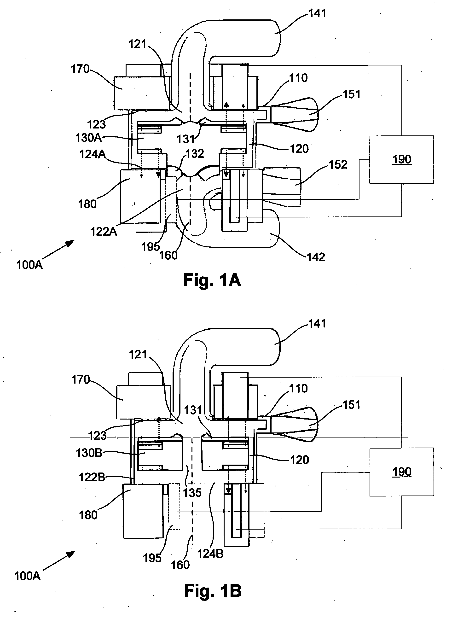
[0196]In this example, the heart pump 100A includes a housing 110 defining a cavity 120, containing an impeller 130A. The impeller 130A effectively divides the cavity 120 into first and second cavity portions 121, 122A. The housing 110 includes first and second inlets 141, 142 and corresponding first and second outlets 151, 152, which are in fluid communication with the first and second cavity portions 121, 122A, respectively. It will be appreciated that the cavity 120 may include volutes (not shown) to assist with transfer of the fluid to the outlets 151, 152.

[0197]The impeller 130A includes first and second sets of vanes 131, 132, such that rotation of the impeller 130A about a rotation axis 160 urges fluid from the inlets 141, 142 to the corresponding outlets 151, 152. In use, rotation of the impeller 130A is achieved using a drive, such as a magnetic drive 170. The magnetic drive 170 typically ...


PUM


Abstract

Apparatus for transporting fluid within a biological subject, the apparatus including an at least partially compliant section, so that the compliant section at least partially controls the flow of fluid therethrough. The compliant section may also be used in conjunction with a heart pump for the purpose of at least partially controlling the flow of blood through the heart pump.

Description

BACKGROUND OF THE INVENTION[0001]The present invention relates to an apparatus for transporting fluid within a biological subject, the apparatus including a compliant section for providing flow control. In one example the apparatus includes either a cannula for transporting fluid such as blood, or a heart pump for pumping blood.DESCRIPTION OF THE PRIOR ART[0002]The reference in this specification to any prior publication (or information derived from it), or to any matter which is known, is not, and should not be taken as an acknowledgment or admission or any form of suggestion that the prior publication (or information derived from it) or known matter forms part of the common general knowledge in the field of endeavour to which this specification relates.[0003]The use of mechanical device therapy to treat heart failure is increasing as the general population ages and the number of donor organs for heart transplantation remains limited. Devices can be used to bridge a patient to hear...

Claims


Application Information

Patent Timeline
Patent Type & Authority Applications(United States)
IPC IPC(8): A61M1/10A61M60/178A61M60/216A61M60/422A61M60/531A61M60/554A61M60/806A61M60/857
CPCA61M1/101A61M1/3659A61M1/1008A61M2205/3334A61M60/857A61M60/148A61M60/554A61M60/422A61M60/216A61M60/178A61M60/531A61M60/806
Inventor TIMMS, DANIELGREGORY, SHAUN DAVIDGADDUM, NICHOLAS RICHARD
Owner TIMMS DANIEL
Why Eureka
Try Eureka