Ratchet Cutting Tool With A Replacement Blade Storage Tray

Active Publication Date: 2014-10-02
RONAN JOHN S
View PDF0 Cites 13 Cited by
  • Summary
  • Abstract
  • Description
  • Claims
  • Application Information

AI Technical Summary

Benefits of technology

The present invention provides an improved ratchet cutting tool for different types of work pieces like plastic tubing, rubber hoses, and non-metallic materials. The tool has a special cutting blade that can be easily replaced by a user without tools. The tool also includes a storage tray for replacing the cutting blade. The tool is designed to have a sufficient mechanical advantage to easily cut different size work pieces with smooth edges without rough or jagged edges.

Problems solved by technology

Also, in these prior art the ratchet-type hand cutting tools, tool maintenance including blade removal and replacement can be cumbersome and time consuming.
For many of these prior art ratchet-type hand-held cutting tools, bulky and cumbersome tools are needed in order to remove and replace the cutting blade and blade holder or plate.
Also, none of the prior art hand-held cutting tools describe a unique display replacement blade storage tray for replacement cutting blades that is slidable along an intermediate side surface between a handle portion and a cradle portion with locking means to removably secure the sliding display storage tray or compartment in a fixed position.
Further, none of the prior art hand-held cutting tools describe the unique ratchet mechanism with a minimum number of ratchet components rather than the cumbersome, complex and multiple components shown in the aforementioned prior art hand-held cutting tools.

Method used


Image

  • Ratchet Cutting Tool With A Replacement Blade Storage Tray
  • Ratchet Cutting Tool With A Replacement Blade Storage Tray
  • Ratchet Cutting Tool With A Replacement Blade Storage Tray

Examples


Embodiment Construction

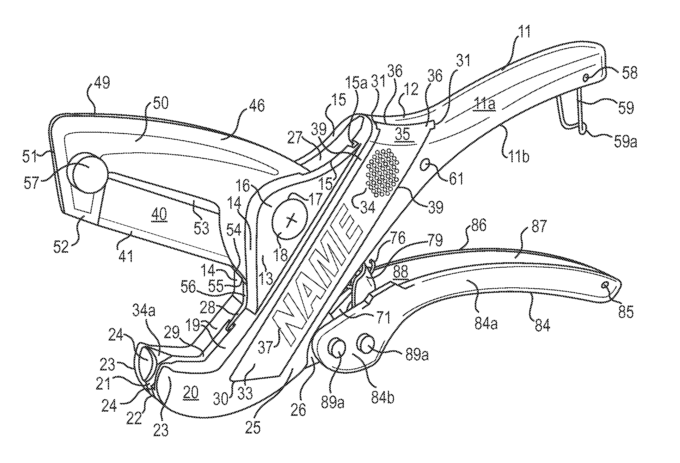
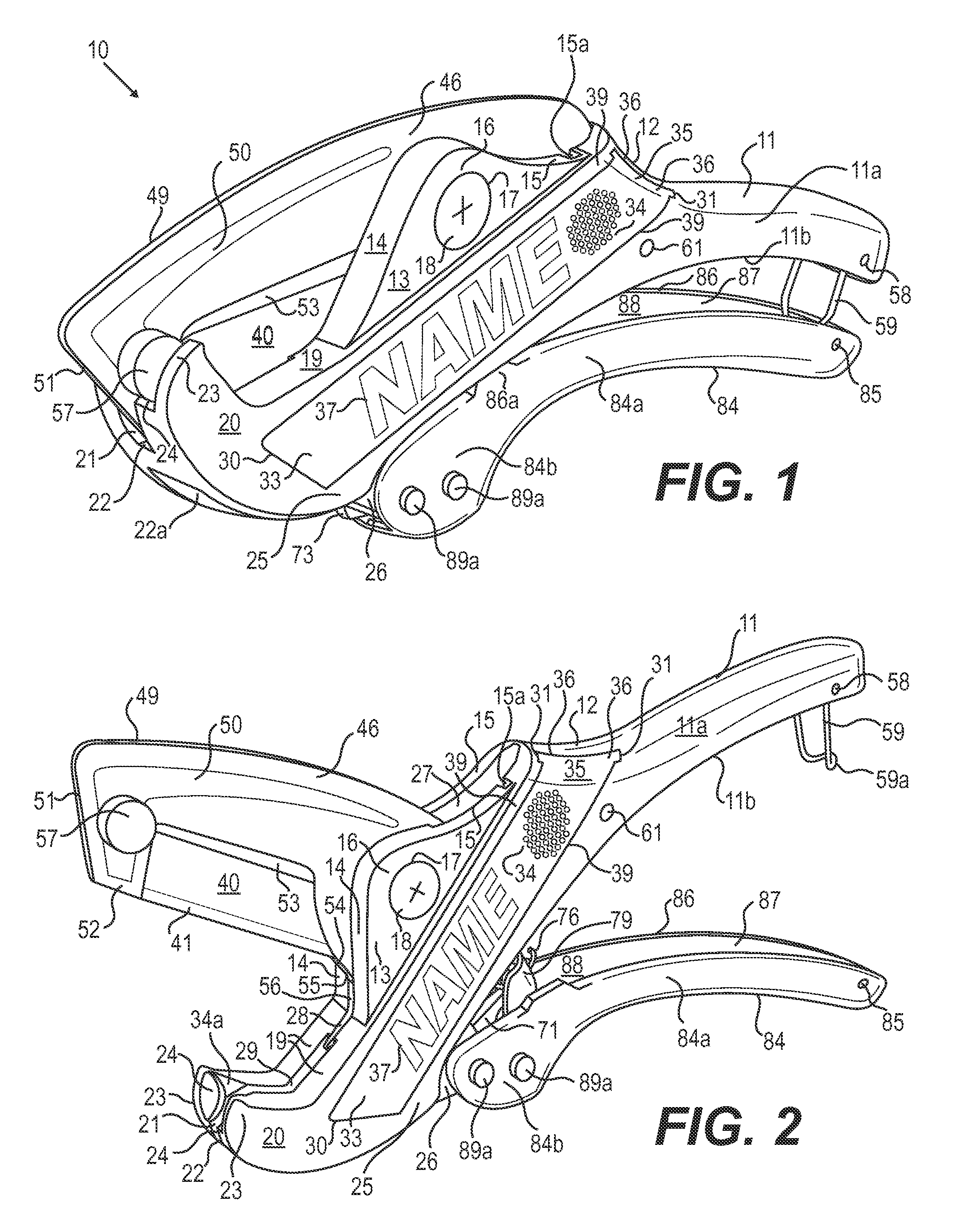
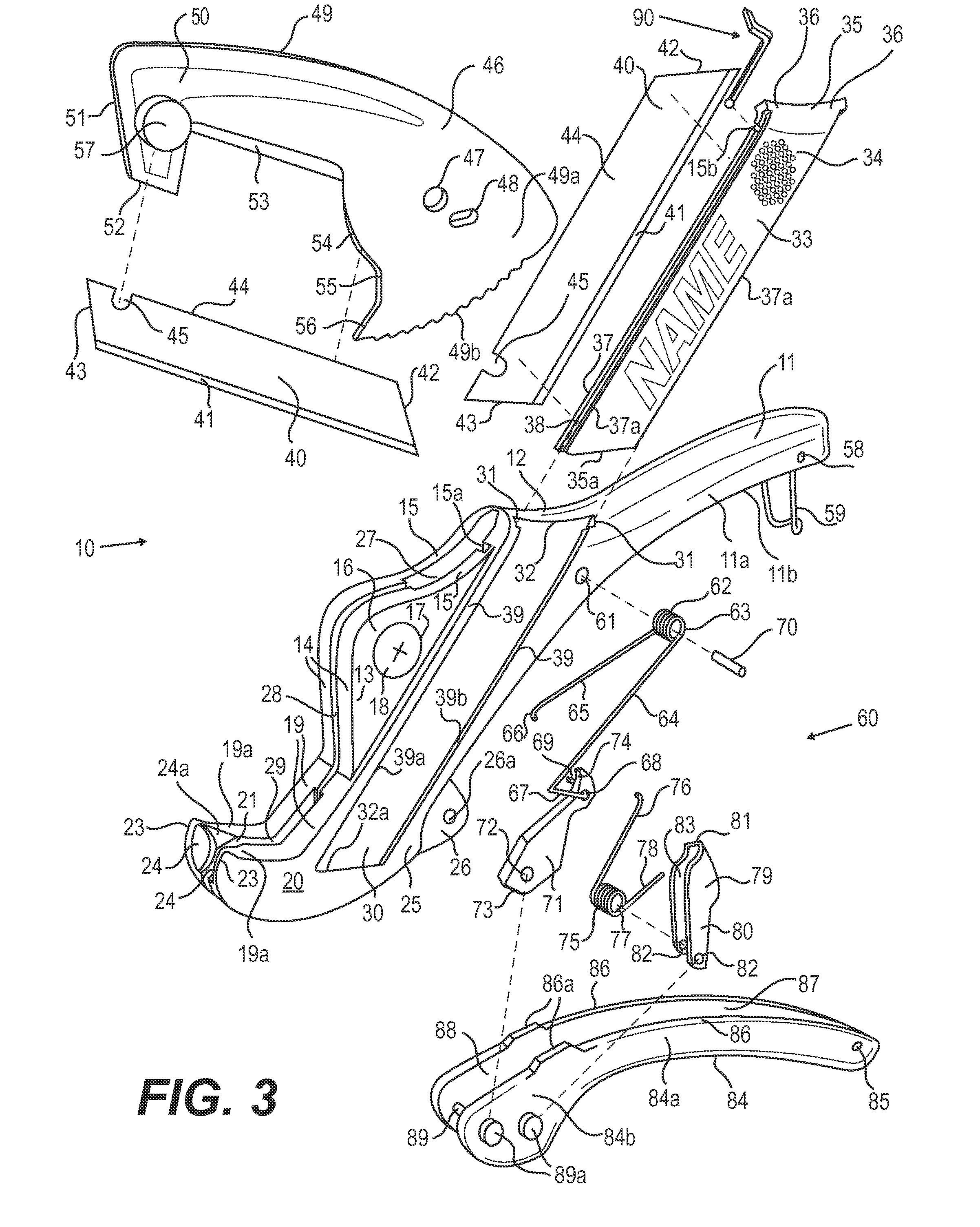
[0035]Reference will now be made in detail to the preferred embodiments of the invention, examples of which are illustrated in the accompanying drawings. While the invention will be described in conjunction with the accompanying drawings, it will be understood that they are not intended to limit the invention to the accompanying drawings. On the contrary, the present invention is intended to cover alternatives, modifications and equivalents, which may be included within the spirit and scope of the invention as defined by the appended claims.

[0036]FIGS. 1-2 of the preferred embodiment of the present invention show an improved ratchet cutting tool with a sliding replacement and display storage tray assembly 10 the ratchet cutting tool in a closed position in FIG. 1 and in an open position in FIG. 2. These Figures which are very similar and will be discussed together to limit the detailed written description The improved ratchet cutting tool assembly 10 includes a first handle member 1...


PUM

PropertyMeasurementUnit
Sizeaaaaaaaaaa
Heightaaaaaaaaaa
Distanceaaaaaaaaaa

Abstract

The improved ratchet cutting tool comprises a first contoured handle member having a first rear end defining a hand gripping portion, a second forward end defining a cradle portion for supporting different size work pieces to be cut. A second contoured handle member having a first rear end defining a hand gripping portion, a second forward end defining a securing means for pivotally attaching a ratchet cutting blade holder and ratchet assembly between the first and second handle members. An intermediate portion including a pair of ramp portions that extends between the cradle portions and the hand gripping portion. The first handle member includes a sliding replacement and display blade storage tray cavity disposed along an exterior side face of the first handle member below the intermediate portion for receiving a sliding replacement and display blade storage tray for storing non-standard angled cutting blades therein.

Description

CROSS REFERENCE TO RELATED APPLICATION(S)[0001]NoneBACKGROUND OF THE INVENTION[0002]1. Field of the Invention[0003]The present invention relates generally to the art of hand-held operated cutting tools or devices with a fixed or replaceable cutting blade, and more specifically to a ratchet-type hand tool for cutting different size work pieces, such as, plastic tubing or pipe conduits, rubber hoses, electrical or telephone cables, and other non-metallic materials. Further the present invention relates to a ratchet blade holder for removably attaching a cutting blade thereto without the use of tools and a sliding blade storage tray or compartment disposed along a surface of the hand-held operated cutting tools for housing replacement cutting blades therein.[0004]2. Description of the Related Art[0005]It is well known that a variety of hand-held operated cutting tools have been utilized for cutting different size plastic tubing or PVC tubing or pipe conduits utilized in both the plumbi...

Claims


Application Information

Patent Timeline
IPC IPC(8): B23D21/10
CPCB23D21/10B26B13/04B26B13/26B26B17/02B26D3/169
Inventor RONAN, JOHN S.
Owner RONAN JOHN S
Why Eureka
Try Eureka