Attachment pylon for a turbine engine

a technology of turbine engines and pylons, which is applied in the direction of machines/engines, air-flow influencers, transportation and packaging, etc., can solve the problems of increasing bpr, difficult to continue on those lines, and drawbacks in integrating engines on airplanes, so as to reduce the interaction between the jet and the wing, increase the flow speed, and reduce the pocket of turbulent kinetic energy

Active Publication Date: 2014-10-02
SN DETUDE & DE CONSTR DE MOTEURS DAVIATION S N E C M A
View PDF6 Cites 5 Cited by
  • Summary
  • Abstract
  • Description
  • Claims
  • Application Information

AI Technical Summary

Benefits of technology

[0009]The presence of deflectors serves to accelerate and deflect a portion of the air flow passing round the pylon for the purpose of reducing the jet noise of the engine. Furthermore, in comparison with the prior art solution of using chevrons, deflectors have the advantage of not constituting an obstacle to the jet leaving the engine.
[0030]In certain embodiments, each series of deflectors has at least two deflectors, and preferably at least three deflectors. This makes it possible to reduce the speed gradients in stages, and thus to have a plurality of shear layers between streams flowing at speeds that are fairly close together.

Problems solved by technology

Nevertheless, increasing the BPR leads to a major drawback in terms of integrating engines on an airplane, since increasing the flow rate of the bypass stream necessarily involves increasing the diameter of the engines.
Unfortunately, nowadays the reasonable limiting size for integrating a turbojet with a ducted fan under an airplane wing would appear to have been nearly reached, and it would seem to be difficult to continue on those lines.
Although that solution is quite effective in acoustic terms, it nevertheless presents a negative effect on the performance of the turbojet under cruising conditions.
Furthermore, the improvements that have been demonstrated remain modest.

Method used


Image

  • Attachment pylon for a turbine engine
  • Attachment pylon for a turbine engine
  • Attachment pylon for a turbine engine

Examples


Embodiment Construction

[0040]Embodiments are described below in detail with reference to the accompanying drawings. These embodiments show the characteristics and the advantages of the invention. It should nevertheless be recalled that the invention is not limited to these embodiments. In particular, although the invention is described below in the context of its application to a turbojet (of the bypass type having two separate streams) that is fastened under an airplane wing, the invention is not limited to this application.

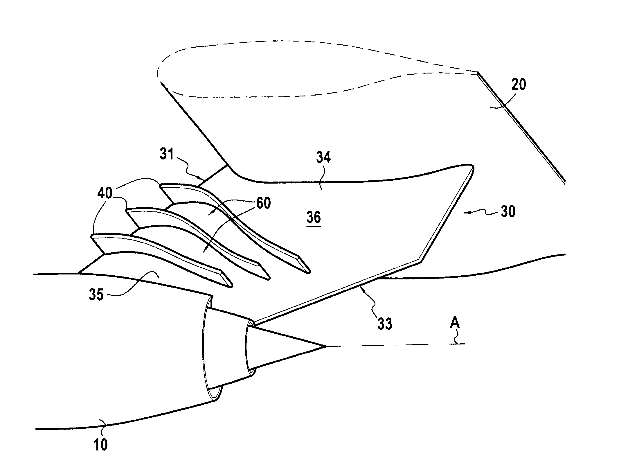
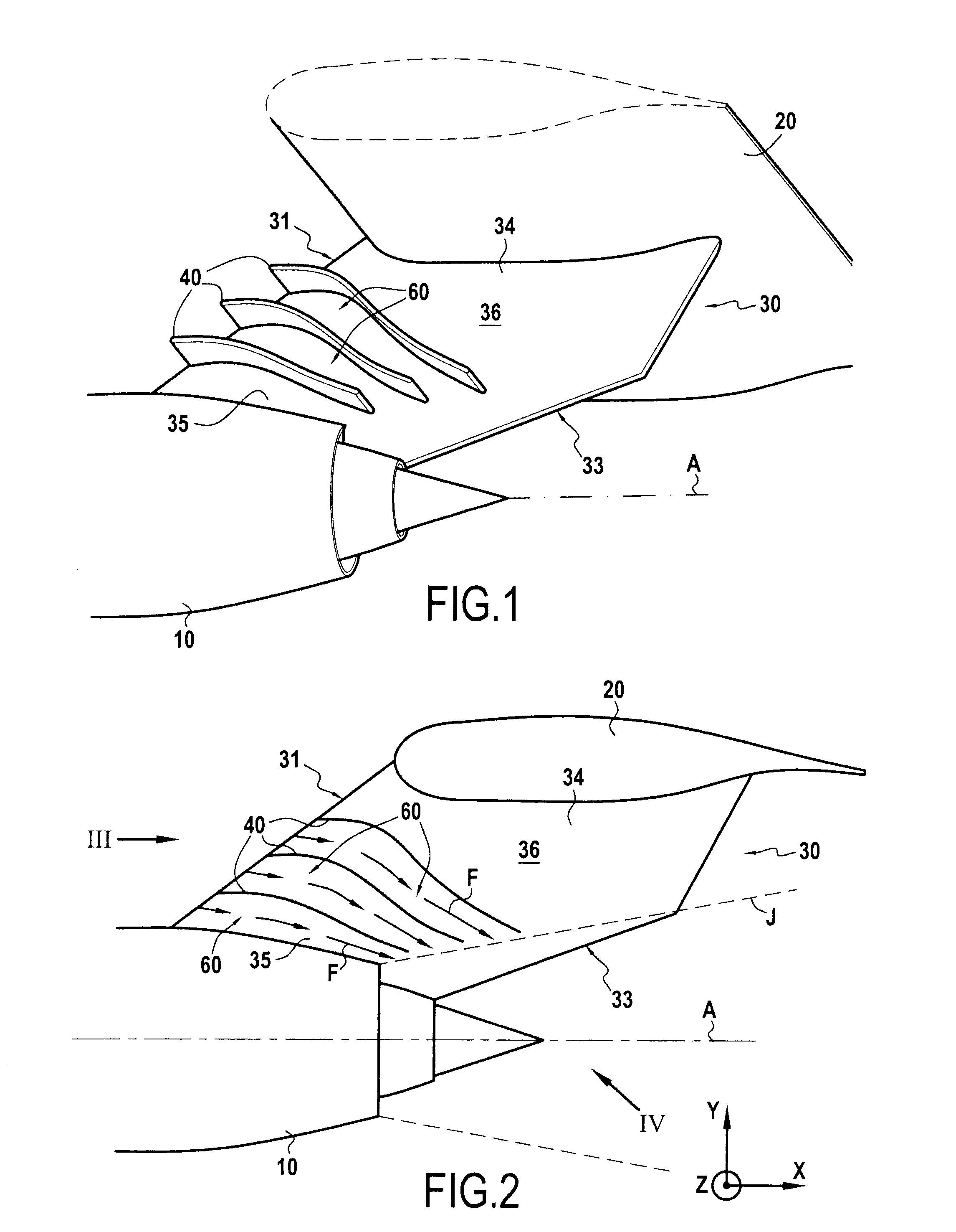
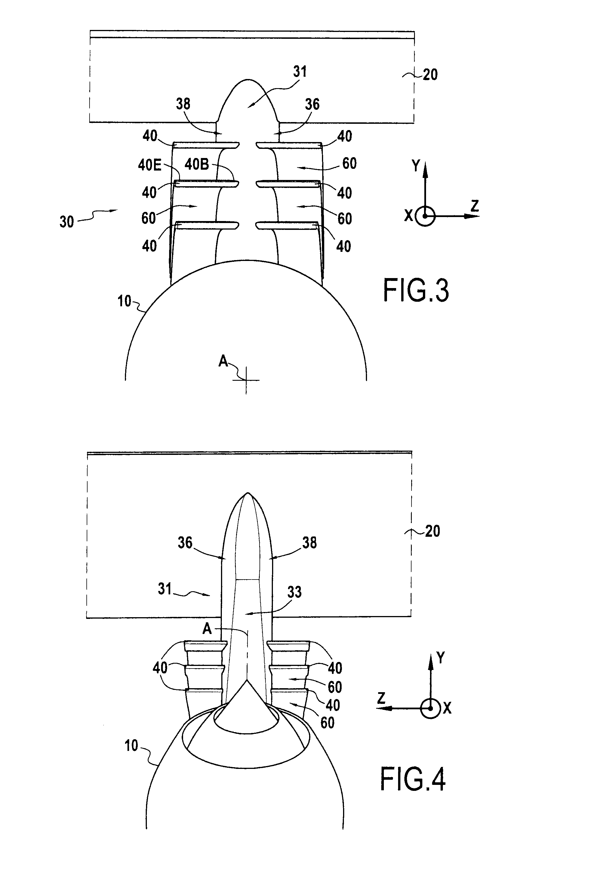
[0041]FIGS. 1 to 4 show a turbojet 10 fastened under an airplane wing 20 by means of an attachment pylon 30. The drive axis A of the turbojet 10 is drawn in chain-dotted lines in the figures.

[0042]The pylon 30 has a streamlined profile defined by two opposite faces 36 and 38 and it extends longitudinally (i.e. parallel to the drive axis A) between a leading edge 31 and a trailing edge 33. The pylon 30 is defined transversely between a distal end 35 fastened to the turbojet 10 and a pr...


PUM


Abstract

A pylon for attaching a turbine engine, the pylon configured to connect the engine to a structural element of an aircraft. The pylon includes a streamlined profile defined by two opposite lateral faces and defined longitudinally between a leading edge and a trailing edge. On each of its lateral faces the pylon includes a series of deflectors that are transversely spaced apart from one another and that define between them convergent and curved channels configured to accelerate air streams flowing within the channels on aircraft takeoff or in flight to deflect the air streams towards a jet of the engine.

Description

FIELD OF THE INVENTION[0001]The present disclosure relates to an attachment pylon (or mast) for a turbine engine, and to an aircraft device including such a pylon.[0002]More particularly, such a pylon may be used to attach a turbojet to the wing of an airplane.STATE OF THE PRIOR ART[0003]The general trend over the last forty years towards reducing engine noise from airplanes, and more particularly from bypass turbojets, has been to increase the bypass ratio (BPR) of such turbojets, i.e. to increase the ratio of the bypass stream to the primary stream leaving the turbojet. Present projects propose engines with a high BPR lying in the range 9 to 12, whereas in the 1970s, BPRs laid in the range 5 to 6. Specifically, for constant thrust, increasing the flow rate of the bypass stream serves to reduce ejection speeds and thereby reduce the noise due to the mixing of the ejection gases. Nevertheless, increasing the BPR leads to a major drawback in terms of integrating engines on an airplan...

Claims


Application Information

Patent Timeline
Patent Type & Authority Applications(United States)
IPC IPC(8): F02C7/20
CPCF02C7/20B64C2230/14B64D29/02Y02T50/10B64C7/02B64C21/10B64C23/00B64D27/18
Inventor BODARD, GUILLAUMEHENRY, CYPRIENJODET, NORMANVUILLEMIN, ALEXANDRE ALFRED, GASTON
Owner SN DETUDE & DE CONSTR DE MOTEURS DAVIATION S N E C M A
Why Eureka
Try Eureka