System for supplying liquefied natural gas fuel and method of operating the same

a technology of liquefied natural gas and system, which is applied in the direction of positive displacement liquid engines, container discharging methods, lighting and heating apparatus, etc., can solve the problems of different temperature and pressure, etc., for driving engines, and achieve the effect of enhancing the operation efficiency of the system and rapid supply of an engin

Active Publication Date: 2014-10-02
HYUNDAI HEAVY IND CO LTD
View PDF2 Cites 9 Cited by
  • Summary
  • Abstract
  • Description
  • Claims
  • Application Information

AI Technical Summary

Benefits of technology

[0021]In a system for supplying LNG fuel and a method of operating the same, LNG is returned in a standby mode, and the LNG is supplied to an engine after the standby mode is completed. Accordingly, a time taken for cooling down the pump after the standby mode is completed is not needed, and thus fuel may be rapidly supplied to a...

Problems solved by technology

However, the temperature and the pressure, etc. for driving ...

Method used


Image

  • System for supplying liquefied natural gas fuel and method of operating the same
  • System for supplying liquefied natural gas fuel and method of operating the same
  • System for supplying liquefied natural gas fuel and method of operating the same

Examples


second embodiment

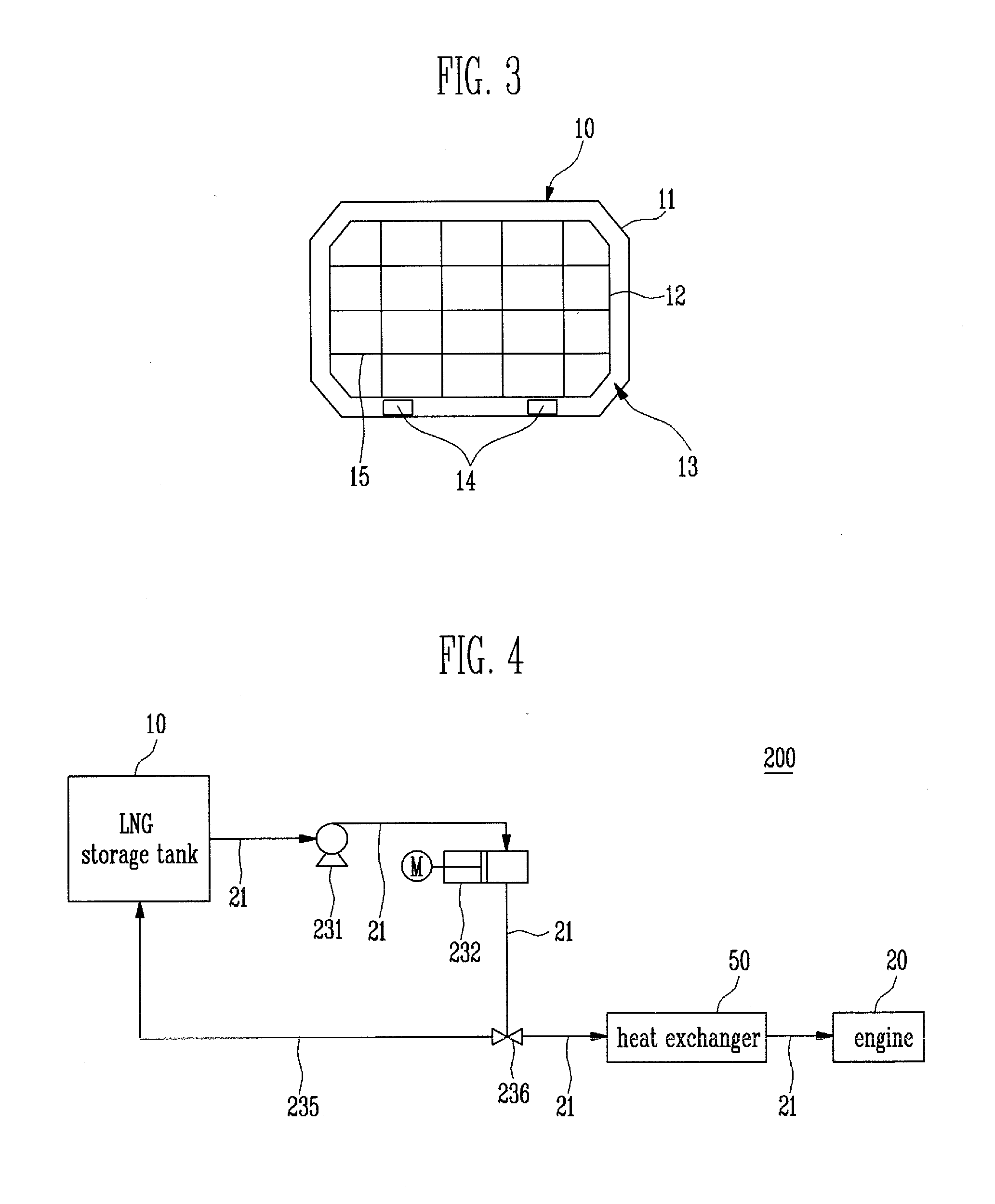
[0066]FIG. 4 is a conceptual view of a system for supplying LNG fuel according to the present invention. Like reference numerals refer to like or corresponding elements, and thus their description will be omitted.

[0067]A system 200 for supplying LNG fuel will be described in detail with reference to FIG. 4. The system 200 is substantially the same as the system 100 except for a cool-down operation of a high pressure pump 232 and an operation of cutting off downstream of a high pressure pump 232. In the first embodiment, the outlet of the high pressure pump 232 is cut off. In the present embodiment, a cool-down operation of the high pressure pump 232 may start after a cool-down operation of the boosting pump 231 is completed. The cool-down operation in the present embodiment may be performed with load lower than normal load, e.g., 60% or more, in the same or similar manner as the cool-down operation of the boosting pump 131 in the first embodiment.

[0068]Since the LNG, outputted from ...

first embodiment

[0073]FIG. 5 is a flowchart illustrating a method of operating the system for supplying LNG fuel according to the present invention.

[0074]As shown in FIG. 5, the method of operating the system 100 in FIG. 2 may include step S110 of cutting off the outlet of the high pressure pump so that the LNG is not outputted from the high pressure pump, step S120 of supplying the LNG from the LNG storage tank to the boosting pump and the high pressure pump, step S130 of returning the LNG supplied to the high pressure pump, step S140 of cooling down the boosting pump, step S150 of operating the boosting pump at a predetermined load, step of S160 of stopping cool-down operation of the boosting pump and the high pressure pump when supplying of the LNG is cancelled, step S170 of completing the cool-down operation of the high pressure pump, and step S180 of normally operating the boosting pump and the high pressure pump.

[0075]At step S110, the outlet of the high pressure pump 132 is cut off so that t...


PUM


Abstract

A system for supplying LNG fuel includes a fuel supplying line connected from an LNG storage tank to an engine, a boosting pump provided on the fuel supplying line and configured to pressurize LNG outputted from the LNG storage tank and cool down in a standby mode, a high pressure pump configured to pressurize the LNG outputted from the boosting pump to high pressure, and a return line connected between the LNG storage tank and the high pressure pump, in which the LNG is returned through the return line.

Description

CROSS-REFERENCE TO RELATED APPLICATION[0001]This application claims priority from Korean Patent Application No. 10-2013-0033192, filed on Mar. 28, 2013, the contents of which are incorporated herein by reference in its entirety.BACKGROUND[0002]An embodiment of the present invention relates to a system for supplying LNG fuel and a method of operating the same.[0003]A ship is a transport vehicle for sailing across the ocean, carrying bulk of minerals, crude oil, natural gas, several thousands of containers, etc. A ship is made of steel and moves by propulsion generated through the rotation of a propeller when it is floating on a water plane by buoyancy.[0004]A ship generates propulsion by driving an engine. The engine moves a piston using a gasoline or diesel and rotates a crankshaft by a reciprocating motion performed by the piston, so that a shaft connected to the crankshaft rotates to drive the propeller.[0005]However, recently, a Liquefied Natural Gas (LNG) carrier is using LNG fu...

Claims


Application Information

Patent Timeline
IPC IPC(8): F17C13/00
CPCF17C13/002F02D19/022F02D19/0647F02M21/0212F02M21/0245F04B23/10F17C13/00F17C2221/033F17C2223/0161F17C2265/066F17C2270/0105Y02T10/30F02D19/02F02M21/02F02M21/06F25B31/006F25B31/008
Inventor LEE, TAE SEOK
Owner HYUNDAI HEAVY IND CO LTD
Why Eureka
Try Eureka