Test system and method

Inactive Publication Date: 2014-10-02
HON HAI PRECISION IND CO LTD
View PDF4 Cites 5 Cited by
  • Summary
  • Abstract
  • Description
  • Claims
  • Application Information

AI Technical Summary

Problems solved by technology

A gas detector is often positioned in a high place or other location that is not convenient for a user to access.
The user must manually operate the gas detector to check whether or not the gas detector works properly, which is very inconvenient.

Method used


Image

  • Test system and method
  • Test system and method
  • Test system and method

Examples


Embodiment Construction

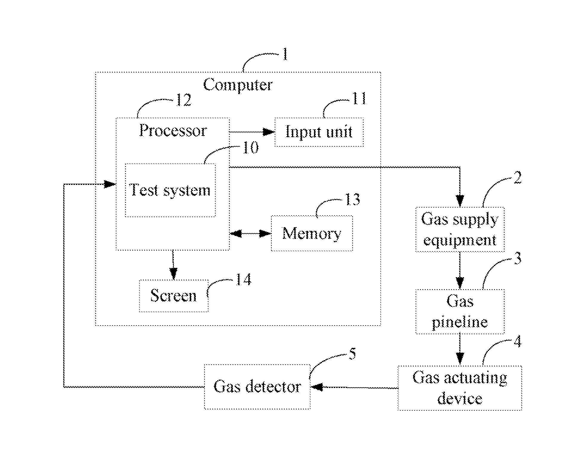
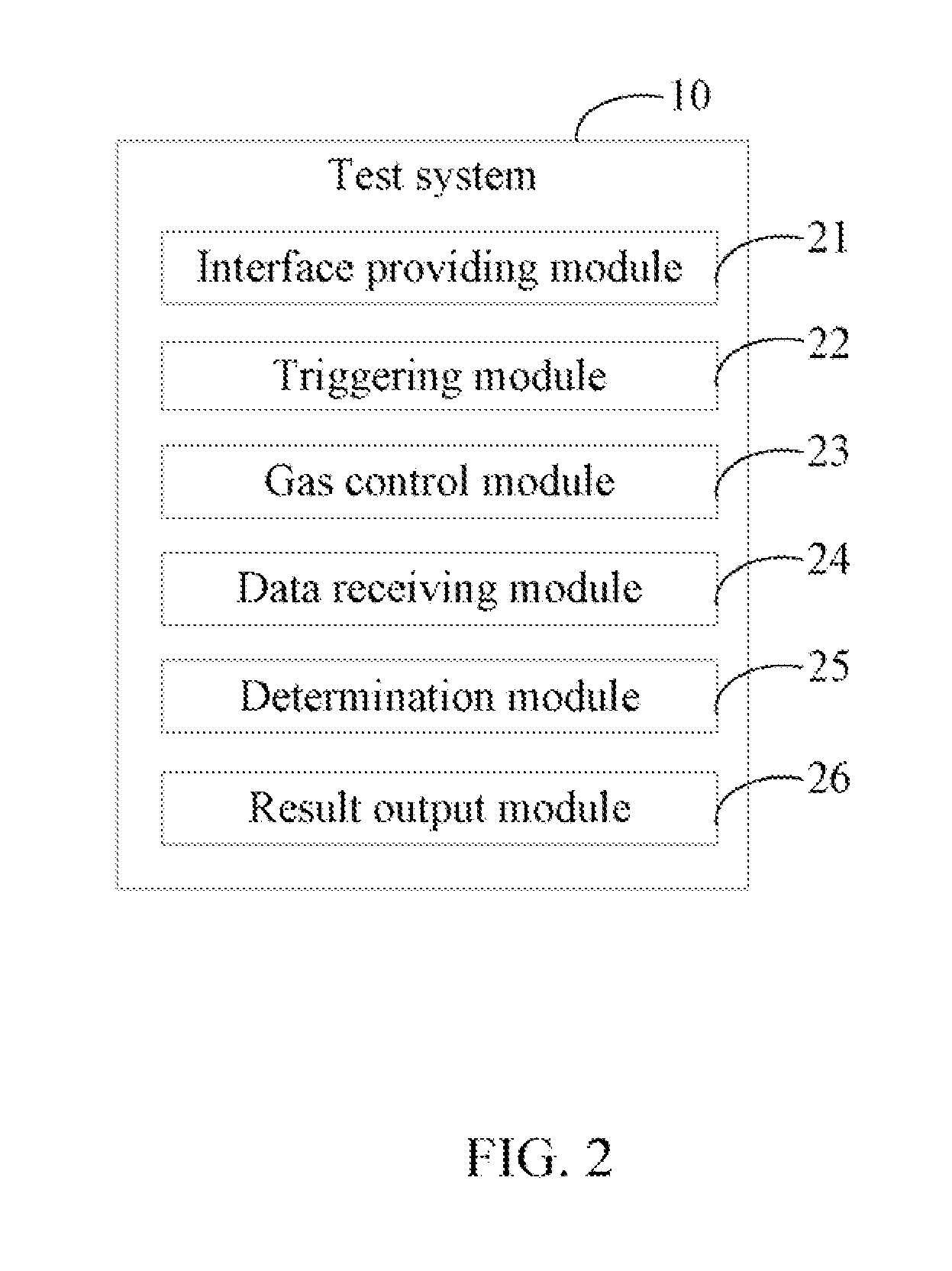
[0010]FIG. 1 is a block diagram of applying a test system 10 in accordance with an exemplary embodiment. The test system 10 is applied to a remote control device. In the embodiment, the remote control device is a computer 1. The test system 10 is utilized to generate a trigger signal to test a gas detector 5 and obtain a test result. In the embodiment, the gas detector 5 is a carbon dioxide detector.

[0011]The computer 1 includes an input unit 11, a processor 12, a memory 13, and a screen 14. The input unit 11 generates input signals in response to a user's input. The processor 12 controls the computer 1 to operate and performs the test system 10. The memory 13 stores data, such as a reference concentration of gas. The screen 14 displays information.

[0012]The computer 1 is electrically connected to gas supply equipment 2 via wiring. The gas supply equipment 2 stores gas, and the computer 1 controls the gas supply equipment 2 to release gas. A gas pipeline 3 is connected to the gas su...


PUM

PropertyMeasurementUnit
concentrationaaaaaaaaaa
pressureaaaaaaaaaa
timeaaaaaaaaaa

Abstract

A test system and a test method adapted for a remote control device are disclosed. The remote control device is electrically connected to gas supply equipment. The gas supply equipment stores gas and is connected to a gas actuating device. A gas detector is near to the gas actuating device. The method includes: providing a test interface, acquiring a gas detector on the test interface and generating a trigger signal to start testing the gas detector; remotely controlling the gas supply equipment to generate high pressure; and controlling the gas actuating device to spew out gas. The method further includes: comparing the concentration of the gas with a stored reference concentration to determine whether or not the gas detector works properly and generating a result.

Description

BACKGROUND[0001]1. Technical Field[0002]The disclosure relates to test technology, and more particularly to a test system for testing a gas detector and a test method adapted for the system.[0003]2. Description of Related Art[0004]A gas detector is often positioned in a high place or other location that is not convenient for a user to access. The user must manually operate the gas detector to check whether or not the gas detector works properly, which is very inconvenient.[0005]Therefore, what is needed is a test system and method to overcome the described shortcomings.BRIEF DESCRIPTION OF THE DRAWINGS[0006]FIG. 1 is a block diagram of applying a test system in accordance with an exemplary embodiment.[0007]FIG. 2 is a block diagram of the test system of FIG. 1.[0008]FIG. 3 is a flowchart of a method for testing a gas detector adapted for the test system of FIG. 2.[0009]FIG. 4 is a schematic view of a test interface for testing a gas detector in accordance with an exemplary embodimen...

Claims


Application Information

Patent Timeline
Patent Type & Authority Applications(United States)
IPC IPC(8): G01N33/00
CPCG01N33/0006G01N33/007
Inventor WANG, SHIH-CHENGCAI, YI-WEN
Owner HON HAI PRECISION IND CO LTD
Why Eureka
Try Eureka