
Pneumatic radial tire for passenger vehicle and method for using the same

a technology for passenger vehicles and radial tires, which is applied to inflatable tyres, special tyres, vehicle components, etc., can solve the problems of deteriorating comfortablility, reducing free space in vehicles, and poor fuel efficiency, and achieves good running performance, high fuel efficiency, and good running performan

Active Publication Date: 2014-10-02
BRIDGESTONE CORP
View PDF6 Cites 28 Cited by
  • Summary
  • Abstract
  • Description
  • Claims
  • Application Information

AI Technical Summary

Benefits of technology

The present invention provides a pneumatic radial tire for passenger vehicles that can run well on both wet and dry road surfaces, while also being efficient with fuel and providing space in the vehicle.

Problems solved by technology

However, increasing widths of tires decreases free space in a vehicle and deteriorates comfortablility therein.
Further, wider widths of tires increase air resistance and cause another problem of poor fuel efficiency.
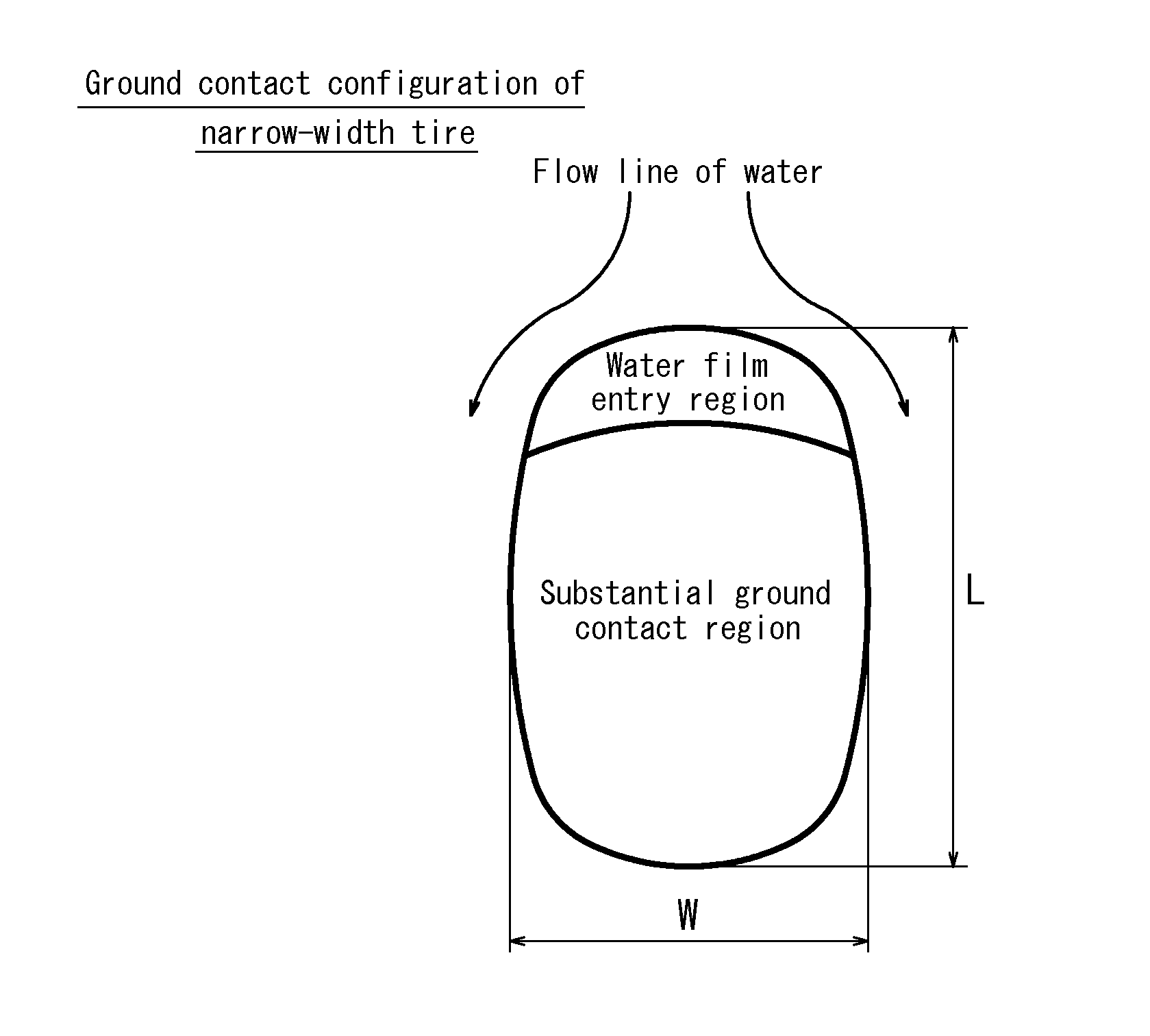
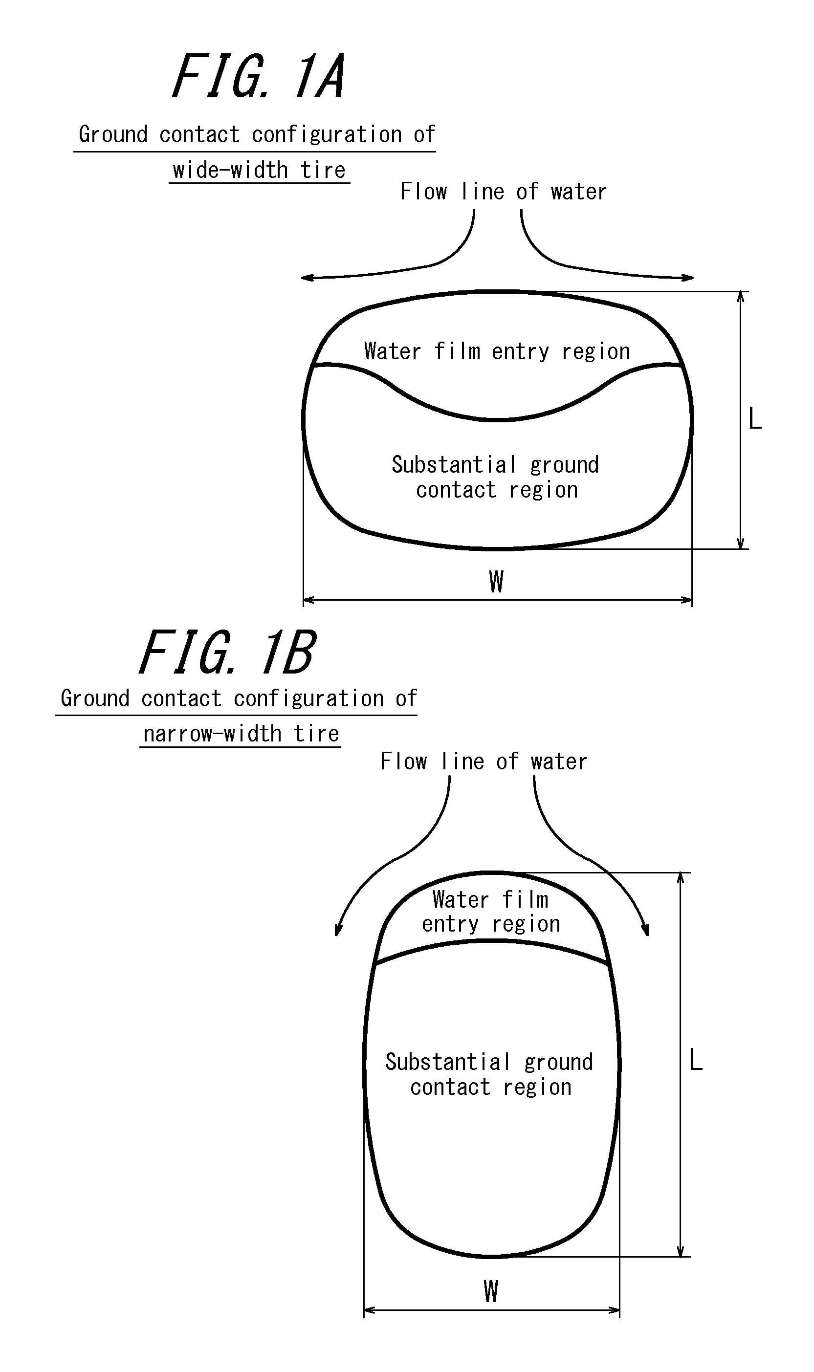
Further, such a wide and flat tire as described above exhibits relatively poor drainage performance because the tire has a relatively wide (ground contact) leading surface and thus water is not smoothly drained on respective sides of the tire in running in a wet condition, as schematically shown by arrows representing water flow lines in FIG. 1A.
In short, the wide and flat tire has a problem of deteriorated wet performance, as well.
However, in a case where a main groove and / or a lug groove having wide groove widths are provided in a tread, there arises a problem in that a negative ratio of the tread increases to decrease a ground contact area and gripping force, thereby deteriorating driving stability and braking performance on a dry road surface and also reducing wear resistance and worsening noise.
Further, in a case where grooves having deep groove depths are provided in a tread, tread rubber must be thick accordingly, which increases tire weight and thus deteriorates running performance of the tire.
However, use of rubber having relatively low hysteresis loss for a tire then causes a problem in that gripping performance of the tire on a wet road surface deteriorates.

Method used


Image

  • Pneumatic radial tire for passenger vehicle and method for using the same
  • Pneumatic radial tire for passenger vehicle and method for using the same
  • Pneumatic radial tire for passenger vehicle and method for using the same

Examples


examples

[0070]Test tires of Examples 1 to 21 and test tires of Comparative Examples 1 to 7 were prepared in order to confirm an effect of the present invention. The detailed characteristics of the respective test tires are shown in Table 4.

In Table 4, “Negative ratio” represents a negative ratio of the main groove(s); “Total length” represents the total length of the auxiliary grooves per unit area of a ground contact surface of the tread; “Width of land portion 3a” represents a width in the tread width direction of the outermost land portion in the tread width direction; and “Width of land portion 3b” represents a width in the tread width direction of the tread-width-direction inner land portion. In the column of “W1 / W2”, two W1 / W2 ratios are shown in combination e.g. (0.1, 0.8), in a case where one type of auxiliary groove extends from one end portion of a land portion and another type of auxiliary groove extends from the other end portion of the land portion such that the one type of aux...


PUM


Abstract

An object of the present invention is to adequately control relationship between a cross sectional width SW and an outer diameter OD of a pneumatic radial tire for a passenger vehicle. Specifically, a ground contact surface 1 of the tread of the pneumatic radial tire for a passenger car of the present invention is provided with either, as a groove, only at least one main groove 2a extending in the tread circumferential direction or, as grooves, only the main groove 2a and at least one auxiliary groove 2b other than the main groove, wherein the auxiliary groove has a groove width≦2 mm in a tread widthwise region and a negative ratio of the main groove 2a is in the range of 12% to 20% (inclusive of 12% and 20%).

Description

TECHNICAL FIELD[0001]The present invention relates to a pneumatic radial tire for a passenger vehicle and a method for using the pneumatic radial tire.BACKGROUND ART[0002]Bias tires having relatively narrow cross sectional widths were predominantly used in vehicles up to around 1960 because vehicles in those days were relatively lightweight, had relatively low cruising speed required thereof and thus did not put so much stress on the tires. However, radial tires having wide and flat structures are predominant these days because good driving stability in high speed running, as well as good wear resistance, is required of tires as highway networks are developed and vehicle speed increases (e.g. PTL 1).[0003]However, increasing widths of tires decreases free space in a vehicle and deteriorates comfortablility therein. Further, wider widths of tires increase air resistance and cause another problem of poor fuel efficiency. There has been increasingly a demand for a better fuel efficienc...

Claims


Application Information

Patent Timeline
Patent Type & Authority Applications(United States)
IPC IPC(8): B60C3/04B60C11/03
CPCB60C11/033B60C3/04B60C11/0306B60C11/032B60C11/1236B60C2011/0341B60C2011/0344B60C2011/0381B60C11/04B60C11/12B60C2011/1209
Inventor HATANAKA, SHINTAROMATSUMOTO, HIROYUKIKUWAYAMA, ISAO
Owner BRIDGESTONE CORP
Learn More