Replaceably Lined Cable Guides and Tensioning Roller for Drill Line Slip and Cut Operations on a Drilling Rig

a technology of tensioning rollers and cable guides, which is applied in the direction of hoisting equipment, printers, instruments, etc., can solve the problems of dangerous proximity of workers to the moving parts of the draw-works, and the concern of rig personnel

Active Publication Date: 2014-10-02
URQUHART JESSE
View PDF16 Cites 21 Cited by
  • Summary
  • Abstract
  • Description
  • Claims
  • Application Information

AI Technical Summary

Benefits of technology

[0006]According to a first aspect of the invention there is provided a cable guide for supporting a slack portion of a drill line of an drilling rig at an overhead position elevated above a draw-works of the drilling rig during a feeding of a new section of the drill line from a supply reel during a slip and cut operation in which a used section of the drill line is removed from the draw works, the cable guide comprising a base member defining a pathway along which the slack portion of the drill line is to be routed, and at least one replaceable wear member configured for removable engagement to the base member in a position lining the pathway defined by the base member such that the drill line moves over a wear surface of the wear member in movement along the pathway.

Problems solved by technology

However, this can create concern for rig personnel in the form of safety risks created by the uncertainly of when the closed loop formed by the sling might break open when the webbing material eventually gives way to the abrasion experienced under movement of the metal wire rope of the drill line over and through the sling.
Another safety concern arises in that rig workers sometimes find it necessary to use manual tools to ‘hammer’ the drill line into grooves provided for same in the draw-works drum, which can place the worker dangerously close to the moving parts of the draw-works.

Method used


Image

  • Replaceably Lined Cable Guides and Tensioning Roller for Drill Line Slip and Cut Operations on a Drilling Rig
  • Replaceably Lined Cable Guides and Tensioning Roller for Drill Line Slip and Cut Operations on a Drilling Rig
  • Replaceably Lined Cable Guides and Tensioning Roller for Drill Line Slip and Cut Operations on a Drilling Rig

Examples


first embodiment

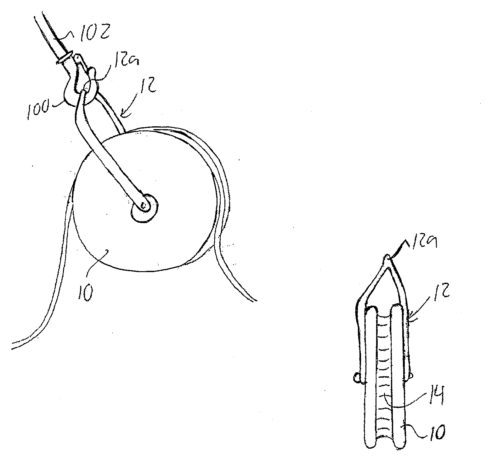
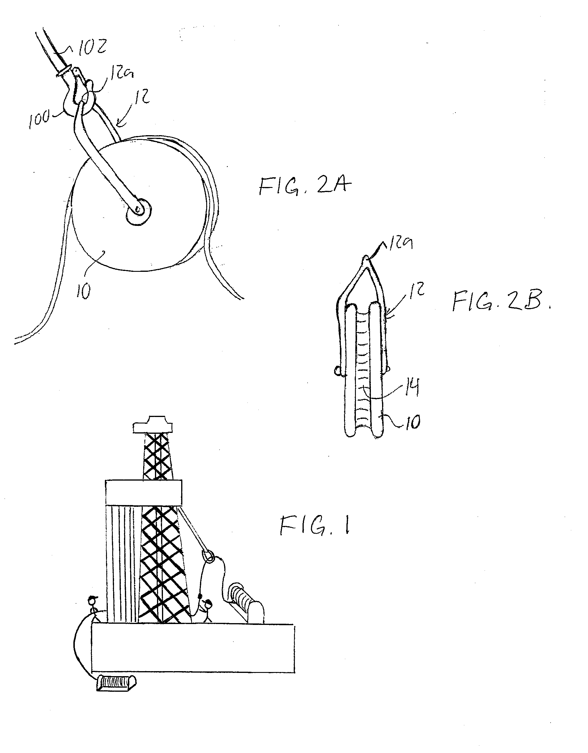
[0043]FIG. 2 shows a first embodiment cable guide that is used directly in place of the prior art sling mentioned above. The cable guide somewhat resembles a conventional pulley in the form of sheave 10 mounted in a support bracket 12. The bracket 12 has a pair of arms at opposite faces of the sheave that extend radially of the sheave and join together at an apex 12a located circumferentially outward from the sheave. However, instead of the sheave being rotatable about its central axis, for example as defined by a central shaft joining together the two arms through a central hole in the sheave, the sheave is fixed in place so as to be non-rotatable about its axis. A sheave liner or insert 14 of suitable wear material, for example nylon or another polymeric material, lines the peripheral groove of the sheave, and presents a concave channel that opens circumferentially outward from the sheeve around the full periphery thereof. The nylon or other material of the insert provides a coeff...

second embodiment

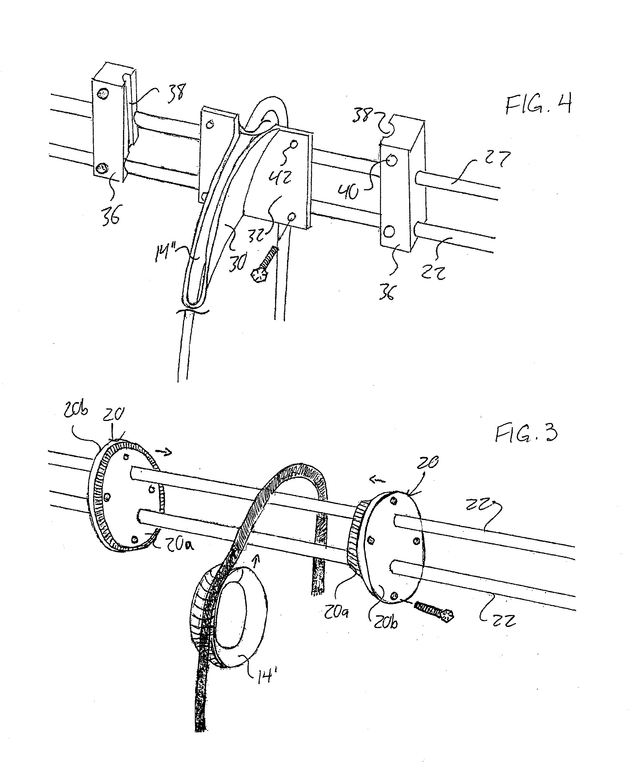
[0045]FIG. 3 shows a second embodiment that again uses a rotationally-fixed sheave-like construction, but forms the sheave from the assembly of two disc-like halves 20 bolted together. At least one of the two discs has an inner portion 20a of reduced-diameter circularly-cylindrical form compared to a larger outer portion 20b of circular plate-like form forming an outer face of the assembled sheave, whereby the peripheral surface of the cylindrical inner portion(s) 20a of the disc(s) forms the peripheral groove of the sheave when the two halves are abutted together at their inner faces, and bolted or otherwise releasably fastened in this assembled condition.

[0046]As shown, the disc-shaped halves 20 may be slidably disposed on a rail or track, for example as defined by two or more parallel shafts 22 or rods running in the axial direction of the round discs. A single-piece ring-shaped liner or insert may form the replaceable wear piece 14′, in which case the sheave is assembled by remo...

third embodiment

[0049]FIG. 4 illustrates a third embodiment in which a somewhat crescent-shaped cable guide member 30 projects outward and downward to one side of a flat mounting plate 32, and features a groove running along its arcuate upper side so that the groove smoothly curves about a horizontal axis parallel to the rotational axis of the draw-works. A replaceable liner 34 of arcuate form is fitted in the arcuate upper groove of the guide member 30 to run from the lower tip thereof to a position overlying the mounting plate, thereby following a pathway over the guide member 30 for the drill line to extend upwardly thereover and down the other side.

[0050]Two mounting blocks 36 are slidably disposed on parallel shafts 22 of the same configuration as the second embodiment, and feature semi-cylindrical channels 38 of vertically upright orientation at their inner sides that face toward one another along the shafts 22, whereby under flush abutment of the remainder of the two blocks' inner faces agai...


PUM


Abstract

Cable guides for overhead support of drill line on a drilling rig during a slip and cut operation feature replaceable liners of wear material supported by a re-usable base. A tensioning roller added to the draw-works resides outward from the periphery of the draw-works drum and is spring-biased toward same into order to force the incoming drill line against the periphery of the drum.

Description

CROSS REFERENCE TO RELATED APPLICATIONS[0001]This application claims benefit under 35 U.S.C. 119(e) of U.S. Provisional Application Ser. No. 61 / 770,002, filed Feb. 27, 2013.FIELD OF THE INVENTION[0002]The present invention relates generally to drilling rigs used in the oil and gas industry, and more particularly to cable guides and tensioning rollers for use in a slip and cut operation in which a new section of drill line is introduced from a storage reel to replace a length of used drill line being cut from the draw-works.BACKGROUND OF THE INVENTION[0003]With reference to the prior art shown in FIG. 1, it is known in a slip and cut operation of the type mentioned above to support slack in the drill line at an overhead position elevated above the draw works while feeding a new section of drill line reeled off of the supply reel to replaced used line that is being cut from the draw-works. For this purpose, it is known to use a sling of webbing material attached to an air tugger line ...

Claims


Application Information

Patent Timeline
Patent Type & Authority Applications(United States)
IPC IPC(8): E21B19/24E21B19/22E21B19/08
CPCE21B19/24B66D1/36E21B19/22E21B19/08E21B19/084
Inventor URQUHART, JESSE
Owner URQUHART JESSE
Why Eureka
Try Eureka