

Token storage device
a technology of token storage and storage device, which is applied in the direction of loop antenna, independent non-interaction antenna combination, instruments, etc., can solve the problems of reducing reading speed, reading speed, and difficulty in reading out a variety of information, and achieve accurate reading out
- Summary
- Abstract
- Description
- Claims
- Application Information
AI Technical Summary
Benefits of technology
Problems solved by technology
Method used
Image

Examples
first embodiment
Chip Tray 100
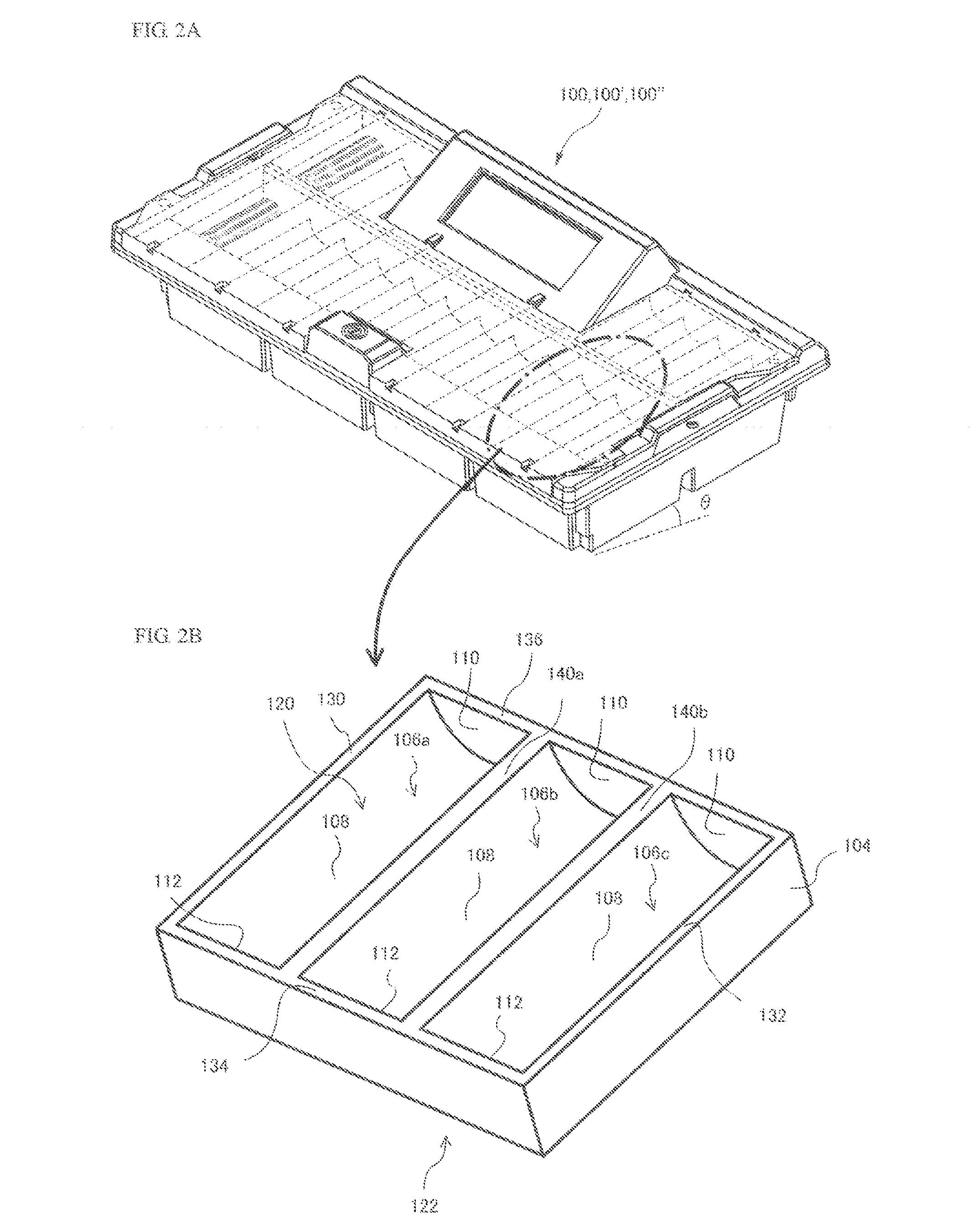
[0070]FIG. 2A is a perspective view illustrating a chip tray 100. FIG. 2B is a perspective view illustrating a surface of a tray unit 104.
[0071]The chip tray 100 is a tray to store gaming chips 300 to be provided to a player and gaming chips 300 collected from a player. The chip tray 100 has tray units 104 and antennas 200. In the present embodiment, a structure in which the antennas 200 are attached to each of the tray units 104 is referred to as a chip tray structure 102.
[0072]In the present embodiment, the chip tray 100 has six tray units 104 (chip tray structures 102). As shown in FIG. 2B, in each of the tray units 104, three chip storing grooves 106a, 106b, and 106c are formed. In each of the chip storing grooves 106a (106b and 106c), a plurality of gaming chips 300, for example, 30 gaming chips 300 can be stored. Each of the tray units 104 is formed of, for example, an opaque plastic material. Each of the tray units 104 has a box-like shape of a rectangular parall...
second embodiment
[0203]FIG. 13 is a perspective view of a back side of a chip tray 100′ according to a second embodiment. FIG. 14 is a sectional front view, taken from a line B-B′ in FIG. 13.
[0204]100′>>>>
[0205]A chip tray structure 102 of the chip tray 100′ has a plurality (two magnetic shielding plates in the present embodiment) of magnetic shielding plates 500 (500a and 500b). When it is not particularly necessary to distinguish the magnetic shielding plates 500a and 500b, the magnetic shielding plates 500a and 500b are simply referred to as magnetic shielding plates 500.
[0206]The chip tray 100′ according to the second embodiment has a configuration similar to that of the chip tray 100 according to the first embodiment except that the magnetic shielding plates 500a and 500b are provided. In the description and drawings of the chip tray 100′ according to the second embodiment, the same components as those of the chip tray 100 according to the first embodiment are denoted with the same reference nu...
third embodiment
[0218]FIG. 15 is a perspective view of a back side of a chip tray 100″ according to a third embodiment. FIG. 16 is a sectional front view, taken from a line C-C′ in FIG. 15.
[0219]100″>>>>
[0220]In the chip tray 100″, a plurality (three antennas in the present embodiment) of antennas 600 (600a, 600b, and 600c) are provided. In addition, when it is not particularly necessary to distinguish the antennas 600a, 600b, and 600c, the antennas 600a, 600b, and 600c are simply referred to as antennas 600.
[0221]As with the second embodiment, each of the magnetic shielding plates 500 is provided between the antennas 600. Specifically, the magnetic shielding plate 500a is provided between the antenna 600a and the antenna 600b. The magnetic shielding plate 500b is provided between the antenna 600b and the antenna 600c. Thus, it can be prevented that the antenna 600 reads out identification information from the IC tags 320 for use in RFID of the gaming chips 300 juxtaposed in the neighboring chip st...
PUM
 Abstract
Description
Claims
Application Information