
A display method, a display control method, and electric device

a display control and display method technology, applied in the field of projection and computing device technology, can solve the problems of increasing the burden on the device, wasting time, and high error response rate, and achieve the effect of accurately responding, accurate operation of objects, and reducing the error response ra

Active Publication Date: 2014-10-02
LENOVO SOFTWARE +1
View PDF5 Cites 6 Cited by
  • Summary
  • Abstract
  • Description
  • Claims
  • Application Information

AI Technical Summary

Benefits of technology

The present disclosure provides a method for displaying and controlling images on a touch-sensitive surface. The method allows for direct interaction with the image, reducing the likelihood of errors and improving user experience. The first device sends the image to the second device, which then sends the information about the interaction to the first device. This allows for quicker and more accurate response to user requests. Additionally, the method reduces the burden on the electronic device by only requiring one response instead of multiple responses.

Problems solved by technology

However, due to the size of small devices and the limitation of accuracy, the results in adopting such manner to identify the user's gesture may cause a higher rate of error response, because the icon of the projection plane that identifies the user's gesture cannot be accurately analyzed.
After an error response, the user needs to re-operate, which not only increases burden on the devices, but also wastes time and creates inconveniences for the user.

Method used


Image

  • A display method, a display control method, and electric device
  • A display method, a display control method, and electric device
  • A display method, a display control method, and electric device

Examples


first embodiment

[0099]The first electronic device is a handheld electronic device, and the second electronic device is a smart TV. The first electronic device has a projecting unit, and the second electronic device has a touch sensing unit. For example, the handheld electronic device may be different electronic devices such as a mobile phone, a PAD, and so on.

[0100]The projection scenario in this embodiment may be the handheld electronic device has a sound outputting unit and a sound acquiring unit, which are provided respectively at both ends of the handheld electronic device. A projection direction of the projecting unit is the same as a first direction, which is a direction from the sound outputting unit to the sound acquiring unit. Specifically, it may be that the projecting unit is provided near the sound acquiring unit, and projects to a direction away from the sound acquiring unit. That is, the scenario of projecting when making a call. The intended use of this embodiment is to enable the us...

second embodiment

[0110]The first electronic device is a handheld electronic device, which is a mobile phone in this embodiment, and the second electronic device is a smart TV. The first electronic device has a projecting unit, and the second electronic device has a touch sensing unit.

[0111]The projection scenario in this embodiment may be the mobile phone has a sound outputting unit and a sound acquiring unit, which are provided respectively at both ends of the mobile phone. A projection direction of the projecting unit is the same as a first direction, which is a direction from the sound outputting unit to the sound acquiring unit. Specifically, it may be that the projecting unit is provided near the sound acquiring unit, and projects to a direction away from the sound acquiring unit. That is, the scenario of projecting when making a call. The intended use of this embodiment is to enable the user to watch the projected content while making a call, and thereby operate the projected content through t...

third embodiment

[0125]The first electronic device is a handheld electronic device, which is a mobile phone in this embodiment; the second electronic device is an AIO or a smart table that is placed horizontally. The first electronic device has a projecting unit, and the second electronic device has a touch sensing unit.

[0126]The projection scenario in this embodiment may be the mobile phone has a sound outputting unit and a sound acquiring unit, which are provided respectively at both ends of the mobile phone. A projection direction of the projecting unit is the same as a first direction, which is a direction from the sound outputting unit to the sound acquiring unit. Specifically, it may be that the projecting unit is provided near the sound acquiring unit, and projects to a direction away from the sound acquiring unit. That is, the scenario of projecting when making a call. The intended use of this embodiment is to enable the user to watch the projected content while making a call, and thereby op...


PUM


Abstract

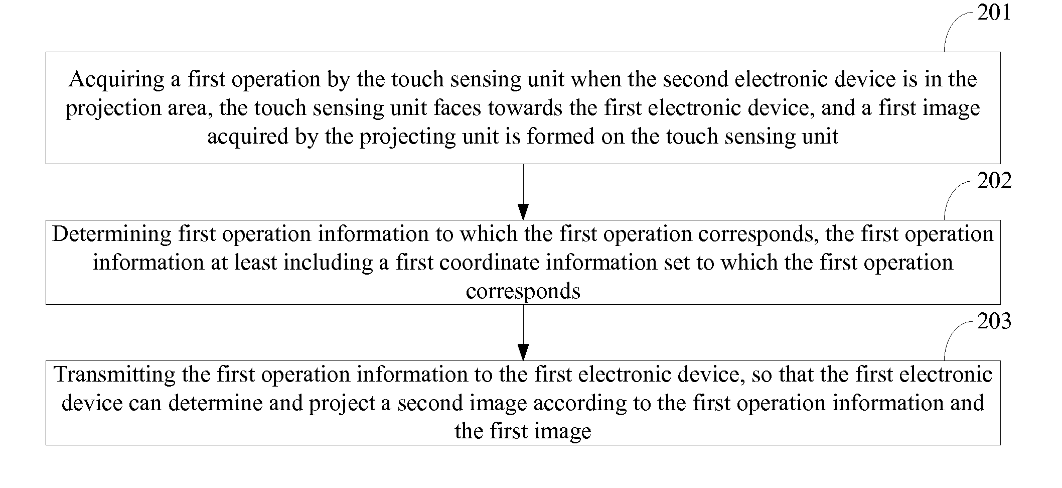
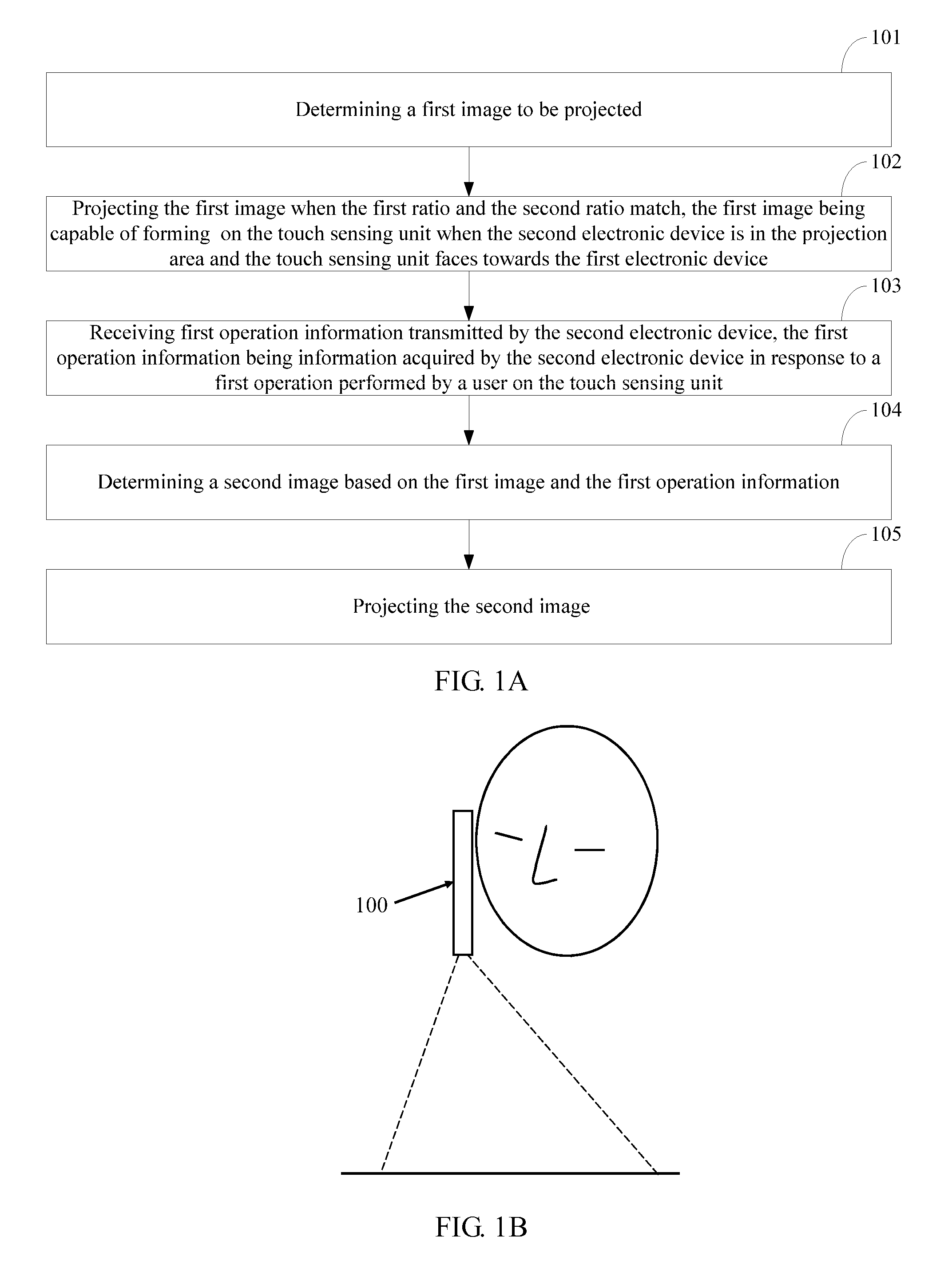
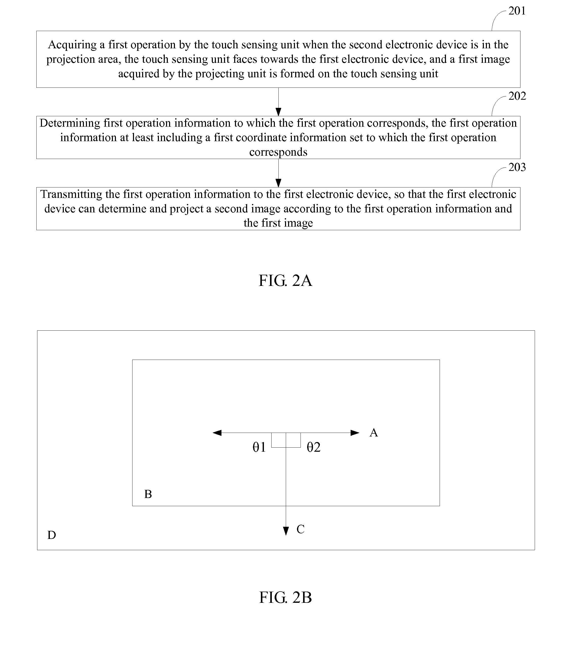
The present invention discloses a display method, for determining user's operations and thereby reducing a rate of error response of electronic devices. The method includes determining a first image to be projected; projecting the first image, the first image being capable of forming on the touch sensing unit when the second electronic device is in the projection area and the touch sensing unit faces towards the first electronic device; receiving first operation information transmitted by the second electronic device, the first operation information being information acquired by the second electronic device in response to a first operation performed by a user on the touch sensing unit; determining a second image based on the first image and the first operation information; and projecting the second image. The present invention also discloses a display control method, and electronic devices for implementing the previously mentioned two methods respectively.

Description

CROSS REFERENCE TO RELATED APPLICATIONS[0001]This application claims the benefit under 35 U.S.C. §119(a) of Chinese Patent Application No. 201310100818.6, filed on Mar. 27, 2013, the entire disclosure of which is incorporated by reference herein in its entirety.TECHNICAL FIELD[0002]The present disclosure relates to the field of projection and computing device technology, and more particularly to a display method, a display control method, and an electronic device.BACKGROUND[0003]With the continuous development of science and technology, electronic technology has been rapidly developed, types of electronic products are more and more diversified, and people enjoy a variety of conveniences brought by science and technology development. Now people can enjoy a comfortable life brought by science and technology developments through various electronic devices.[0004]In the prior art, projectors are not limited to large projectors, there are many small electronic devices, such as tablet PCs ...

Claims


Application Information

Patent Timeline
Patent Type & Authority Applications(United States)
IPC IPC(8): G06F3/042
CPCG06F3/0421G06F3/017G06F3/0425
Inventor HE, ZHIQIANG
Owner LENOVO SOFTWARE
Learn More