Vehicle lamp unit

Inactive Publication Date: 2014-10-02
KOITO MFG CO LTD
View PDF5 Cites 4 Cited by
  • Summary
  • Abstract
  • Description
  • Claims
  • Application Information

AI Technical Summary

Benefits of technology

[0014]According to such a configuration, adjustment of the apparent incline of the twisted end edge can be made. Namely, it is possible to adjust the incline of the second cutoff line of the second light distribution pattern Appr

Problems solved by technology

However, the incline of the twisted end edge that is employed in projectio

Method used


Image

  • Vehicle lamp unit
  • Vehicle lamp unit
  • Vehicle lamp unit

Examples


Example

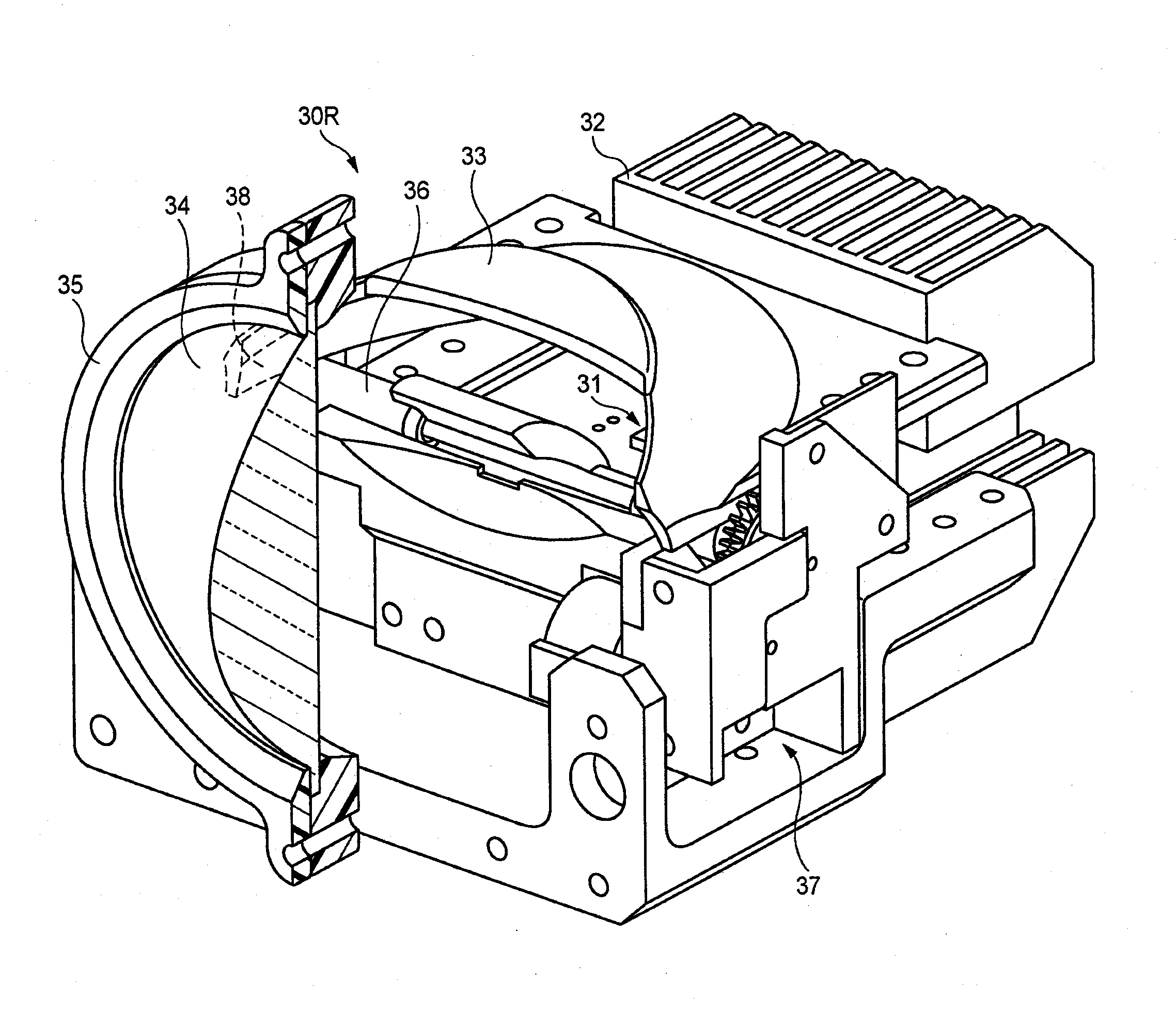
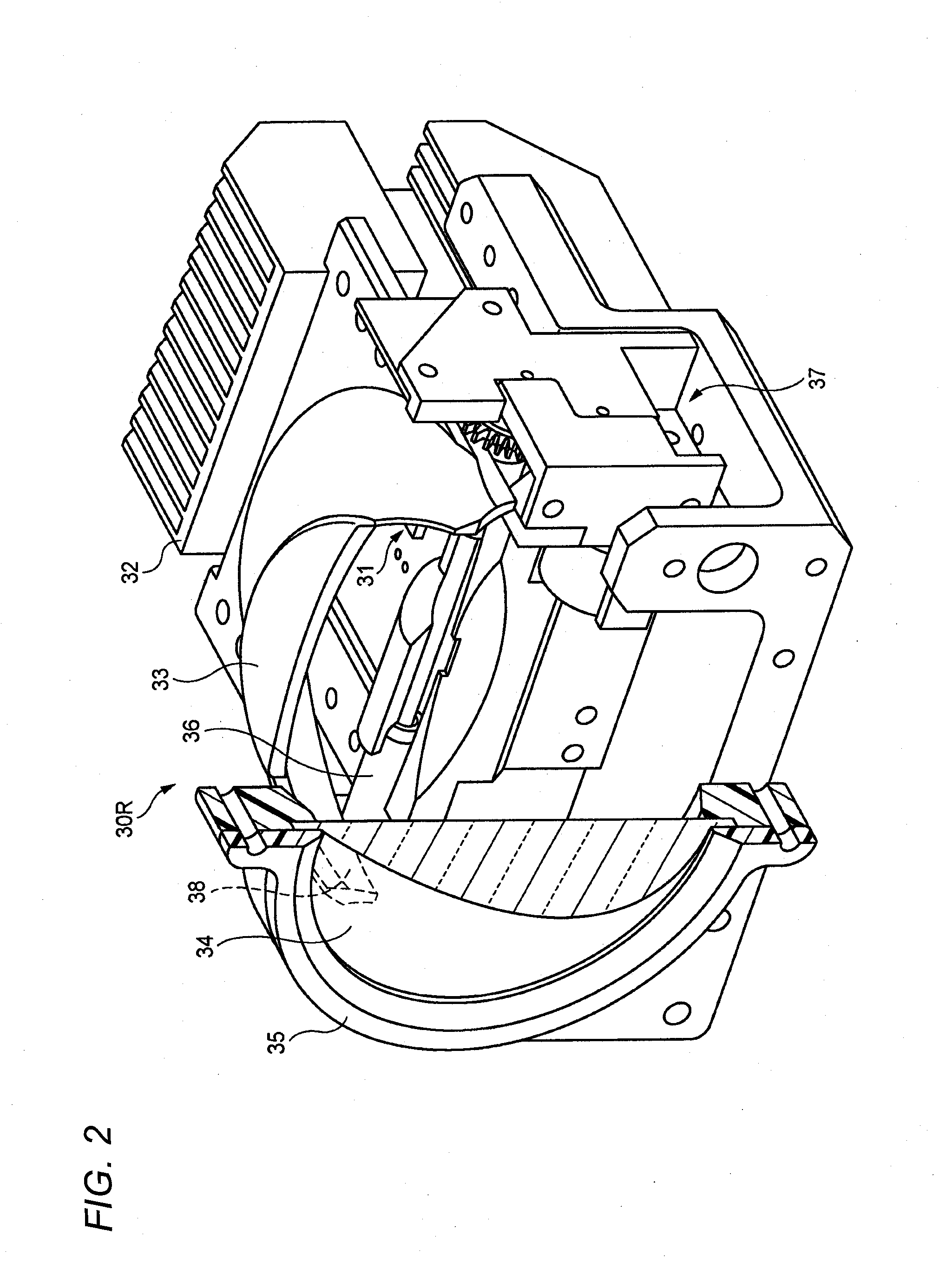
[0026]Detailed description is given below regarding an example of an exemplary embodiment of the invention with reference to the drawings provided. Note that in each of the drawings used in the following description the scale of each member has been modified where appropriate to a size that makes each section recognizable.

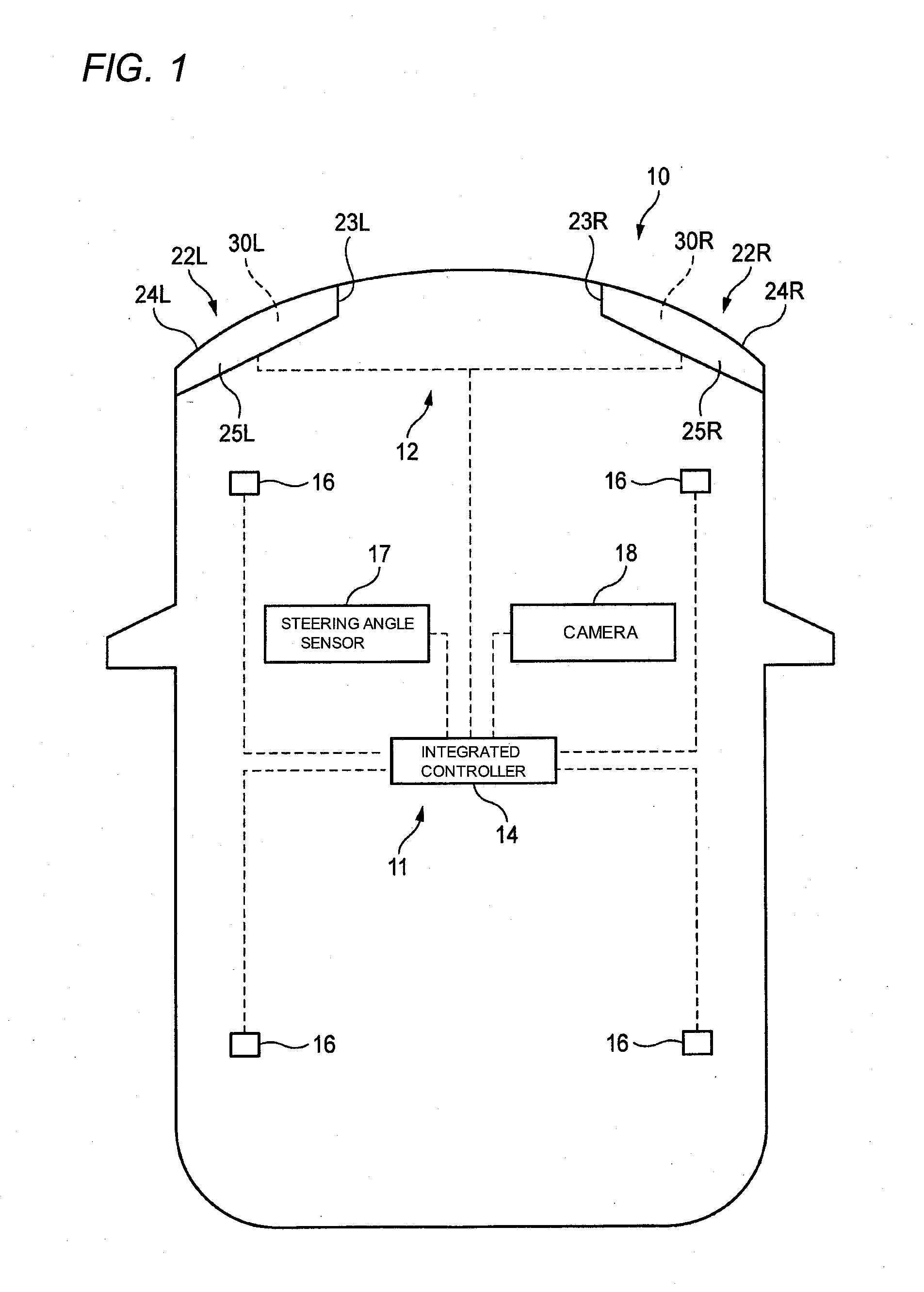
[0027]An overall configuration of a vehicle 10 to which a headlamp device 12 of the exemplary embodiment of the invention is installed is schematically illustrated in FIG. 1. The headlamp device 12, an integrated controller 14, car wheel speed sensors 16, a steering angle sensor 17, and a camera 18 configure a headlamp control system 11.

[0028]The integrated controller 14 is provided with for example: a CPU that executes various types of computation processing; ROM that stores various types of control program; and RAM that is used as a work area for data storage and program execution. The integrated controller 14 performs various controls in the vehicle 10.

[0029]The...


PUM


Abstract

There is provided a lamp unit which is to be installed in a vehicle. The lamp unit includes a light source; a projector lens; a rotary shade that is disposed behind the projector lens so as to block a portion of the light emitted from the light source and that has a rotation axis; and a drive mechanism that rotates the rotary shade about the rotation axis. The rotary shade includes: a first end edge; a second end edge; and a twisted end edge that extends around the rotation axis so as to intersect with the first end edge and the second end edge. A first inclination angle is formed between the rotation axis and a first imaginary plane that is orthogonal to an optical axis of the projector lens.

Description

CROSS-REFERENCE TO RELATED APPLICATION[0001]This application claims priority from Japanese Patent Application No. 2013-066565, filed on Mar. 27, 2013, the entire contents of which are hereby incorporated by referenceBACKGROUND[0002]1. Technical Field[0003]The present disclosure relates to a lamp unit installed to a headlamp of a vehicle.[0004]2. Background Art[0005]Known lamp units of this type are provided with a component known as a rotary shade. A rotary shade is a component with a rotation axis that extends in a vehicle left-right direction, and plural light blocking plates with mutually different end edge shapes are provided at different angle positions around the circumferential direction (see, for example, JP-A-2011-5992).[0006]The rotary shade is rotated about the rotation axis to provide one of the plural light blocking plates on a light path between a light source and a projector lens. A portion of light emitted by the light source is thereby blocked, and the shape of an e...

Claims


Application Information

Patent Timeline
IPC IPC(8): F21V1/10F21S8/10F21W107/10F21Y101/00
CPCF21S48/14F21V1/10B60Q1/085B60Q2300/056B60Q2300/112B60Q2300/122B60Q2300/41B60Q2300/42B60Q2300/45F21S41/148F21S41/155F21S41/698F21W2102/15
Inventor MATSUMOTO, AKINORI
Owner KOITO MFG CO LTD
Why Eureka
Try Eureka