Multipolarity epicardial radiofrequency ablation

a radiofrequency ablation and multipolar technology, applied in the field of medical devices, can solve the problems of exposing patients to undesired risks, limited operation range of existing therapeutic approaches, etc., and achieve the effects of extending the thermal transfer range, and reducing the risk of infection

a radiofrequency ablation and multipolar technology, applied in the field of medical devices, can solve the problems of exposing patients to undesired risks, limited operation range of existing therapeutic approaches, etc., and achieve the effects of extending the thermal transfer range, and reducing the risk of infection

US20140296850A1Active Publication Date: 2014-10-02MEDTRONIC ABLATION FRONTIERS

Image

  • Multipolarity epicardial radiofrequency ablation
  • Multipolarity epicardial radiofrequency ablation
  • Multipolarity epicardial radiofrequency ablation

Examples


Embodiment Construction

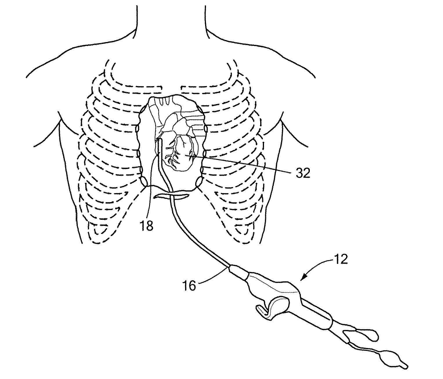
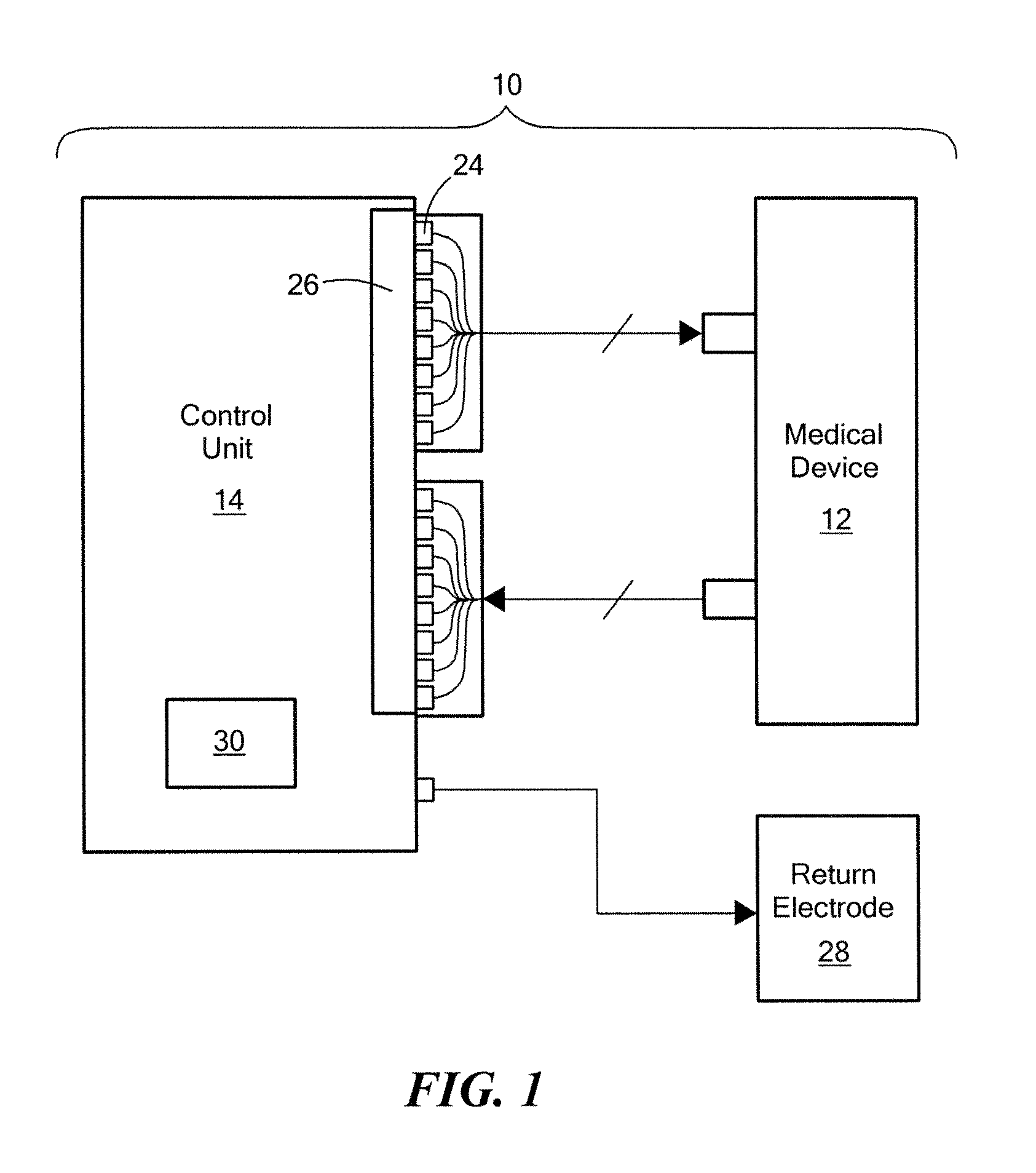
[0024]The present invention advantageously provides a system and methods of use thereof for achieving an extended range of thermal transfer while ablating tissue more effectively and to a greater depth. Referring now to the drawing figures in which like reference designations refer to like elements, an embodiment of a medical system constructed in accordance with principles of the present invention is shown in FIG. 1 and generally designated as “10.” The system 10 generally includes a medical device 12 that may be coupled to a control unit 14 or operating console.

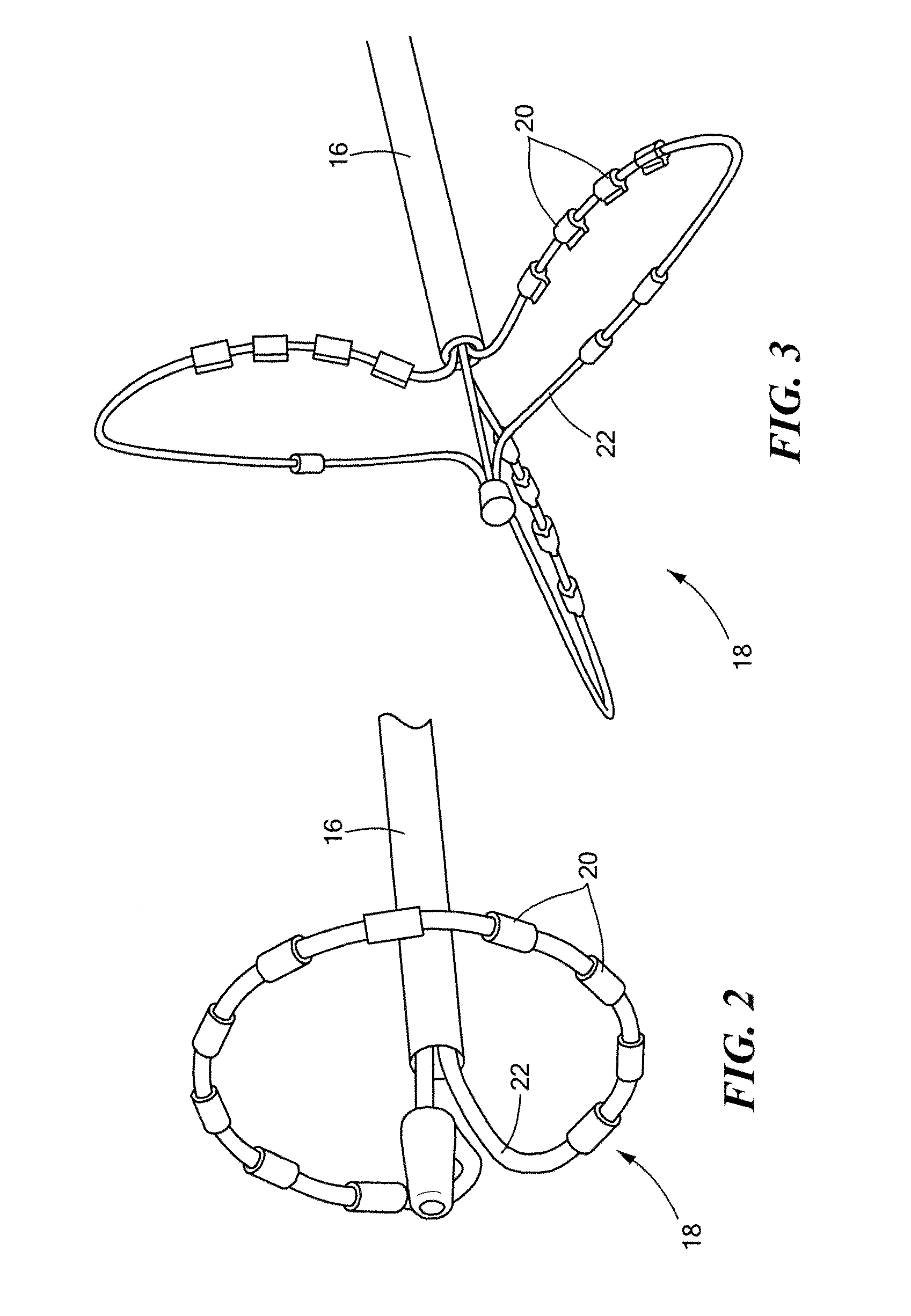
[0025]Referring now to FIGS. 2-6, the medical device 12 may include an elongate body 16 passable through a patient's vasculature and / or insertable through a minimally invasive opening proximate to a targeted tissue region for diagnosis or treatment. The elongate body 16 may define a proximal portion (not shown) having a handle or other controllable implement accessible to an end-user. The medical device 12 may also include ...


PUM


Abstract

A method of ablating an epicardial tissue region, including positioning a medical device adjacent the epicardial tissue region, the medical device having a first electrode, a second electrode, and a third electrode located in between the first and second electrodes; delivering an irrigation fluid to the tissue region; and ablating at least a portion of the tissue region by sequentially activating the third electrode in a monopolar radiofrequency delivery mode and activating the first and second electrodes in a bipolar radiofrequency delivery mode.

Description

CROSS-REFERENCE TO RELATED APPLICATION[0001]This application is a divisional of patent application Ser. No. 12 / 984,675, filed Jan. 5, 2011, entitled MULTIPOLARITY EPICARDIAL RADIOFREQUENCY ABLATION, the entirety of which is incorporated herein by reference.STATEMENT REGARDING FEDERALLY SPONSORED RESEARCH OR DEVELOPMENT[0002]n / aFIELD OF THE INVENTION[0003]The present invention relates to medical devices and methods of use thereof, and in particular towards medical devices for the thermal treatment of tissue.BACKGROUND OF THE INVENTION[0004]Minimally invasive devices are often employed for medical procedures, including those involving ablation, dilation, and the like. In a particular situation, an ablation procedure on may involve creating a series of inter-connecting or otherwise continuous lesions in order to electrically isolate tissue believed to be the source of an arrhythmia. Such lesions may be created using a variety of different energy transmission modalities, such as cryogen...

Claims


Application Information

Patent Timeline
02 Oct 2014
Publication
US20140296850A1
IPC
A61B18/14
CPC
A61B18/1492; A61B2018/00029; A61B2018/00267; A61B2218/002; A61B2018/00577; A61B2018/00821; A61B2018/1407; A61B2018/00363
Inventors
CONDIE, CATHERINE R.; AHLBERG, SARAH E.