Electrode for Radiofrequency Tissue Ablation

a radiofrequency tissue and electrode technology, applied in the field of electrodes for radiofrequency tissue ablation, can solve the problems of excessive coagulation and carbonization of tissue and blood, difficult coagulation, and only a target part is necrotized,

Active Publication Date: 2008-06-19
RF MEDICAL
View PDF6 Cites 21 Cited by
  • Summary
  • Abstract
  • Description
  • Claims
  • Application Information

AI Technical Summary

Benefits of technology

[0010]In order to achieve the above-described object of the invention, there is provided an electrode for radiofrequency tissue ablation, including: a horn-shaped closed end sharpened to its one end; a hollow tube type electrode extended long in the length direction from the other end of the closed end; an insulation member installed on the outer circumference of the hollow electrode except for the part connected to the closed end; at least one temperature sensor installed on the outer circumference of the hollow electrode to be positioned inside the insulation member, for sensing an ambient temperature; and a control unit connected to the hollow electrode and the temperature sensor, for deciding coagulation and necrosis of the tissue according to the temperature sensed by the temperature sensor, and controlling the output supplied to the hollow electrode.

Problems solved by technology

However, the tissue and blood are excessively coagulated and carbonized near the electrode for radiofrequency tissue ablation.
It is thus difficult to coagulate and necrotize only a target part by maintaining a pre-determined temperature in an accurate ablation part.

Method used


Image

  • Electrode for Radiofrequency Tissue Ablation
  • Electrode for Radiofrequency Tissue Ablation
  • Electrode for Radiofrequency Tissue Ablation

Examples


first embodiment

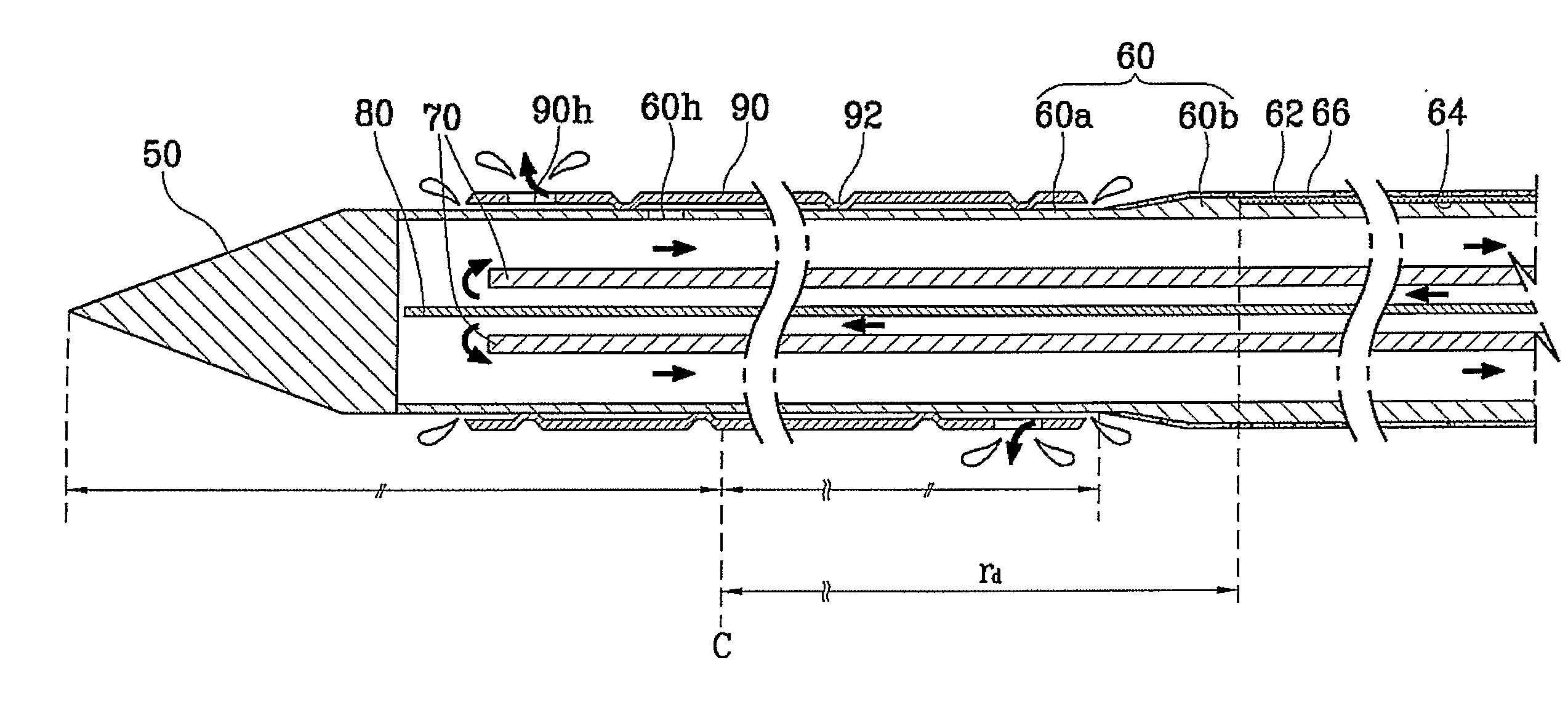
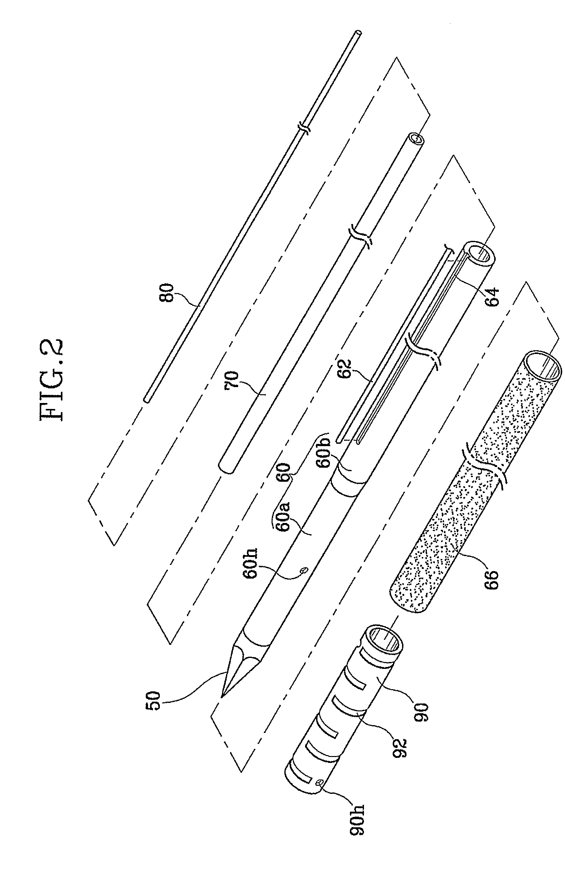
[0024]FIGS. 2 and 3 are a disassembly perspective view and a side-sectional view illustrating an electrode for radiofrequency tissue ablation in accordance with the present invention.

[0025]In accordance with the first embodiment of the present invention, referring to FIGS. 2 and 3, a hollow tube type electrode 60 formed long in the length direction and made of a material in which an output (radiofrequency electric energy) flows is connected to a closed end 50 having a sharp end. The hollow electrode 60 is more thickened than the general one. A mounting groove 64 is formed long in the length direction on the outer circumference of the hollow electrode 60 with a predetermined gap from the closed end 50, so that a temperature sensor 62 can be mounted thereon. In a state where the temperature sensor 62 is mounted on the mounting groove 64, an insulation member 66 is covered on the outer circumference of the hollow electrode 60 except for the part connected to the closed end 50.

[0026]The...

second embodiment

[0051]FIGS. 4 and 5 are a disassembly perspective view and a side-sectional view illustrating an electrode for radiofrequency tissue ablation in accordance with the present invention.

[0052]The second embodiment of the present invention is almost identical to the first embodiment described above. As illustrated in FIGS. 4 and 5, the hollow electrode 60 includes two hollow tubes, namely, an inner tube 61a and an outer tube 61b. The closed end 50 is coupled to the end of the inner tube 61a, and the outer tube 61b is installed with a predetermined gap from the closed end 50. The temperature sensor 62 and the electric wire are installed on a mounting hole 65 formed on the outer tube 61b to be connected to the control unit. The insulation member 66 is covered on the whole outer circumference of the outer tube 61b.

[0053]Here, the inner tube 61a is a hollow tube having a smaller thickness than the general electrode. The closed end 50 is coupled to the end of the inner tube 61a by soldering...

third embodiment

[0068]FIGS. 6 and 7 are a disassembly perspective view and a side-sectional view illustrating an electrode for radiofrequency tissue ablation in accordance with the present invention.

[0069]The third embodiment of the present invention is almost identical to the second embodiment described above. As shown in FIGS. 6 and 7, the closed end 50 is coupled to the end of the inner tube 61a, and the outer tube 61b on which the mounting hole 65 is formed is installed to cover the outer circumference of the inner tube 61a with a pre-determined gap from the closed end 50. The temperature sensor 62 and the electric wire are installed on the mounting hole 65 formed on the outer tube 61b to be connected to the control unit. The insulation member 66 is covered on the whole outer circumference of the outer tube 61b. The part of the inner tube 61a which is not covered with the insulation member 66 generates radiofrequency electric energy, thereby coagulating and necrotizing the peripheral tissue. Th...


PUM


Abstract

The present invention discloses an electrode for radiofrequency tissue ablation which can coagulate and necrotize a tissue by radiofrequency electric energy. The electrode for radiofrequency tissue ablation precisely coagulates and necrotizes a target part of the tissue by sensing a temperature of the tissue. The electrode includes a horn-shaped closed end sharpened to its one end, a hollow tube type electrode extended long in the length direction from the other end of the closed end, an insulation member installed on the outer circumference of the hollow electrode except for the part connected to the closed end, at least one temperature sensor installed on the outer circumference of the hollow electrode to be positioned inside the insulation member, for sensing an ambient temperature, and a control unit connected to the hollow electrode and the temperature sensor, for deciding coagulation and necrosis of the tissue according to the temperature sensed by the temperature sensor, and controlling the output supplied to the hollow electrode.

Description

TECHNICAL FIELD[0001]The present invention relates to an electrode for radiofrequency tissue ablation which can coagulate and necrotize a tissue by radiofrequency electric energy, and more particularly, to an electrode for radiofrequency tissue ablation which can coagulate and necrotize a target part of a tissue by sensing a temperature of the tissue.BACKGROUND ART[0002]There has been suggested a method for coagulating or ablating a target tissue with radiofrequency energy by inserting a long hollow tube type electrode into the tissue. Here, a radiofrequency output is transmitted to the tissue to heat the tissue, so that the tissue and blood vessel can be coagulated by more or less complicated biochemical equipment. Such a process is carried out by coagulation of a cell (including tissue, blood vessel and blood) by heat distortion of protein in the cell over about 55° C.[0003]However, the tissue and blood are excessively coagulated and carbonized near the electrode for radiofrequenc...

Claims


Application Information

Patent Timeline
Patent Type & Authority Applications(United States)
IPC IPC(8): A61B18/14
CPCA61B18/1477A61B2018/00791A61B2018/00023A61B2018/00029A61B18/14
Inventor CHOI, JUNG-SOOK
Owner RF MEDICAL
Why Eureka
Try Eureka