Solar Heat Collection and Storage System

a solar energy and storage system technology, applied in solar heat storage, lighting and heating apparatus, greenhouse gas reduction, etc., can solve the problems of inherently more expensive construction of plumbing without cracks than ductwork with small cracks, fluid in outdoor pipes can leak, and the number of inherent engineering problems have been discovered. , to achieve the effect of reducing system air friction and saving electricity

Inactive Publication Date: 2014-10-09
KLINKMAN PAUL M
View PDF6 Cites 12 Cited by
  • Summary
  • Abstract
  • Description
  • Claims
  • Application Information

AI Technical Summary

Benefits of technology

[0013]It is a further need to devise a solar heating system that conserves electricity by reducing system air friction.

Problems solved by technology

Most forced air systems using rock beds have been susceptible to mildew growth in the rock bed, mildew caused by occasional warm, moist air filtering through a relatively cold bed of rocks in summer, so that water condenses onto all the rocks inside the rock bed.
However, a number of inherent engineering problems have been discovered with fluid-based heat collection.
For starters, plumbing without any cracks is inherently more expensive to build than duct work with small cracks.
Fluid in outdoor pipes can leak, and leaks are expensive.
Water can cause rust and rot.
Water cracks pipes open when it freezes.
Finally, water can boil off or explode with too much heat.
However, some antifreeze compounds are toxic to pets when they leak out, and other antifreeze compounds decay with time.
Pure propylene glycol congeals at low temperatures, wearing out pumps.
Finally, all fluids and pipes strong enough to hold fluids have mass, and many old roofs are unsuitable for heavy heat collection systems.
One engineering problem with planar solar heat collector arrays is susceptibility to high wind gusts.

Method used


Image

  • Solar Heat Collection and Storage System
  • Solar Heat Collection and Storage System
  • Solar Heat Collection and Storage System

Examples


Embodiment Construction

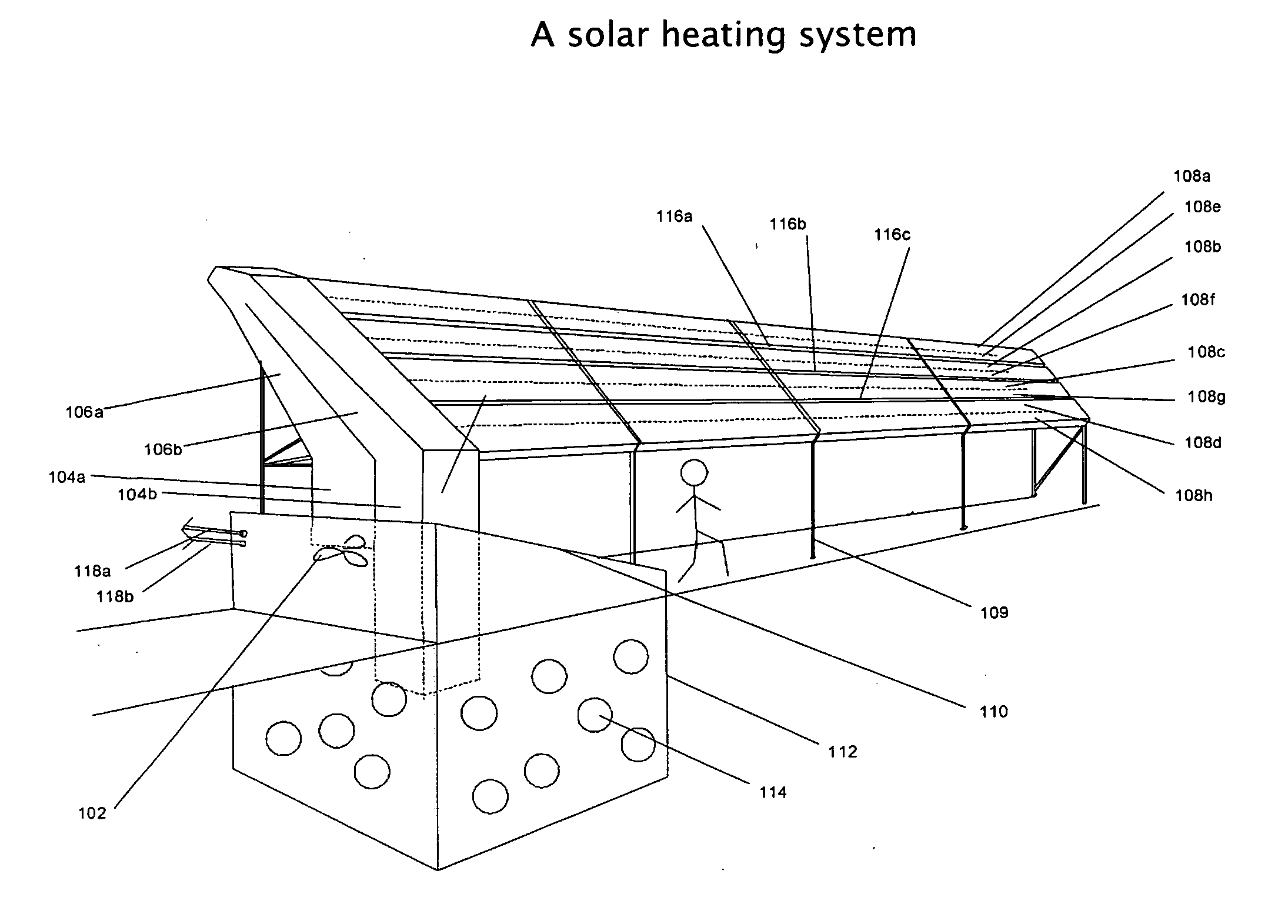
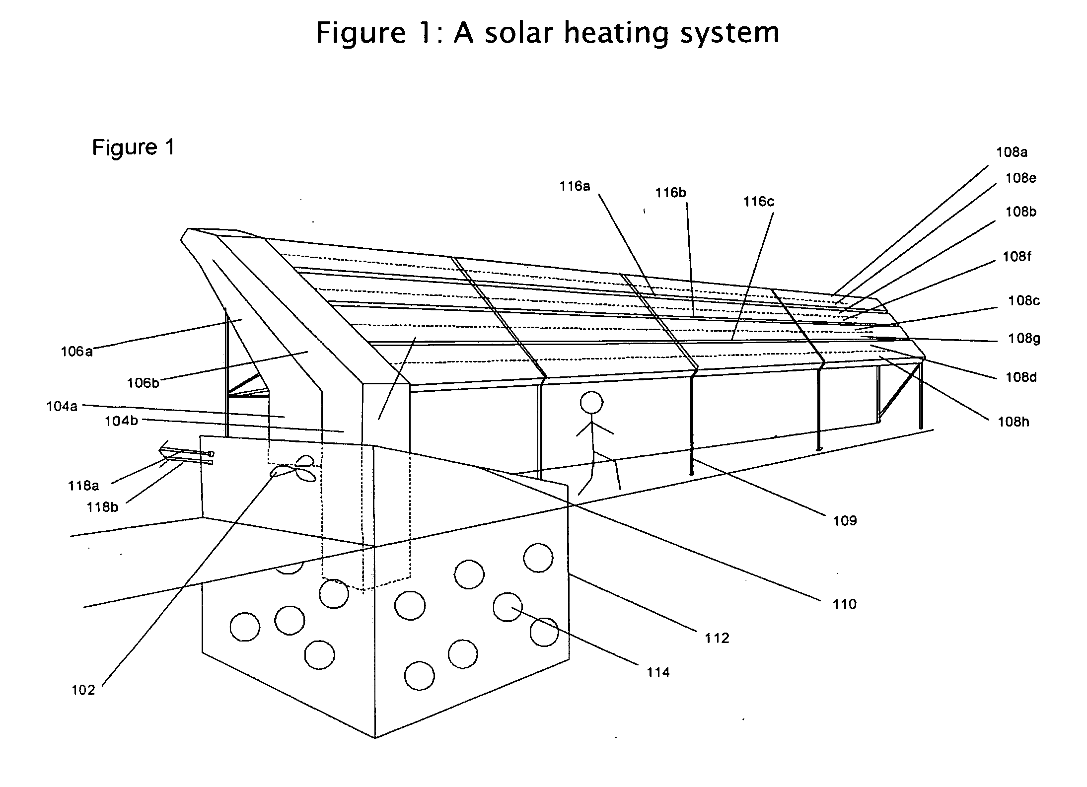
[0030]In the embodiment shown in FIG. 1, air is blown by a fan (102) up a main insulated supply duct (104a), through the insulated supply duct in a manifold (106a) into one of several horizontal raceways (108a-d) mounted on a frame (109), back through a return raceway (108e-h), back through the insulated return duct in the manifold (106b), back down the insulated main return duct (104b), through the roof (110) of an insulated rock bed heat storage building (112), through the rock bed (114) and back to the fan. The dividers between adjoining supply and return ducts may be, but don't necessarily have to be, insulated dividers.

[0031]In this embodiment the air raceways are separated from each other by wind gaps (116a-c), designed to spill some of the uplift and lateral forces of extreme wind gusts. Regular small air gaps in a solid surface, constituting perhaps 10% of the surface's area, will reduce wind-generated overpressures on that surface by perhaps 40%.

[0032]In this embodiment, pi...


PUM


Abstract

An active solar air heat storage system slowly transfers heat into water, providing heat while keeping mold and dust out of a building. A series of bidirectional air ducts separated by periodic wind gaps reduces an overhead collector array's uplift in high winds. Splitting a rock bed's airflow into multiple air channels slows air velocity and reduces air friction in the rock bed. A circular rock bed made partly of concrete blocks is held together by bands around the circle's outside. Solar heat may be gathered under driveways and walkways. A standard set of driveway bricks will allow gentle curves in the driveway while retaining a closed airflow under the driveway. Radiant heat may be trapped inside a collector.

Description

[0001]REFERENCES CITEDU.S. PatentsPat.No.TitleIssue date3,902,474Solar heat converterSep. 2, 19754,060,195Solar heating control systemNov. 29, 19774,207,868Solar Energy SystemJun. 17, 19804,349,012Solar heating controlSep. 14, 19824,452,229Thermal heat storage and cooling systemJun. 5, 19844,469,086Solar heated building structure and methodSep. 4, 1984of operating a solar-heat collector system4,478,210Solar Heating SystemOct. 23, 19845,339,798Modular home systemAug. 23, 19946,701,914Installation for storing thermal energyMar. 9, 20047,823,582Method and apparatus for solar collectorNov. 2, 2010with integral stagnation temperaturecontrol7,954,321Solar power plant and method and / orJun. 7, 2011system of storing energy in a concentratedsolar power plant8,181,642Light absorber deviceMay 22, 201212 / 813,052An Improved Diagonal Solar ChimneyApplied forJun. 10, 2010FIELD OF THE INVENTION[0002]This invention relates generally to heating and air conditioning, and, more particularly, to solar-dr...

Claims


Application Information

Patent Timeline
Patent Type & Authority Applications(United States)
IPC IPC(8): F24J2/34F24J2/20F24S10/50
CPCF24J2/20F24J2/34Y02E10/44Y02B10/20F28D20/0056Y02E70/30F24S20/64F24S20/67F24S10/502F24S10/25F24S2080/502F24S60/00Y02E60/14
Inventor KLINKMAN, PAUL M.
Owner KLINKMAN PAUL M
Why Eureka
Try Eureka