Pneumatic tire

a technology of pneumatic tires and tires, applied in the field of pneumatic tires, can solve the problems of reducing the rigidity affecting the performance of the vehicle, so as to achieve favorable dry performance and wet performance, prevent the collapse of the land portion, and improve snow performan

Active Publication Date: 2014-10-09
BRIDGESTONE CORP
View PDF12 Cites 9 Cited by
  • Summary
  • Abstract
  • Description
  • Claims
  • Application Information

AI Technical Summary

Benefits of technology

[0013]According to a pneumatic tire of the present invention, the edge components oriented in the tire width direction and in the tire circumferential direction are formed on a surface (tread surface) that is in contact with a road surface. As a result, during driving on a snowy road, the edge effect (frictional force due to digging-up) is exerted. Furthermore, the sipe located in the vicinity of the land portion surface is bent in a direction (tire circumferential direction) perpendicular to a sipe longitudinal direction (tire width direction) in the depth direction, and accordingly, when the sipe is opened and the edges dig up snow on a road, an increased part of the land portion penetrates into snow, and snow performance is further improved. On the other hand, in a depth region (land portion's bottom-side part) located on the radially inner side of the tire than the vicinity of the land portion surface, inner wall surfaces of the land portion subdivided by the sipe come into contact with each other. Due to the resulting neighbor interaction, collapse of the land portion is prevented. Consequently, the footprint area of the land portion is sufficiently maintained, and favorable dry performance and wet performance are ensured.
[0014]Thus, the present invention makes it possible to simultaneously achieve, in a pneumatic tire provided with sipe(s) in land portion(s), snow performance, dry performance, and wet performance all at a high level in a single land portion.

Problems solved by technology

However, increasing the number of the sipes in the land portion excessively will lead to subdivision of the land portion, resulting in a decrease in rigidity of the land portion.
Consequently, although snow performance is improved, a footprint area of the land portion is decreased, and dry performance and wet performance might be deteriorated.

Method used


Image

  • Pneumatic tire
  • Pneumatic tire
  • Pneumatic tire

Examples


first embodiment

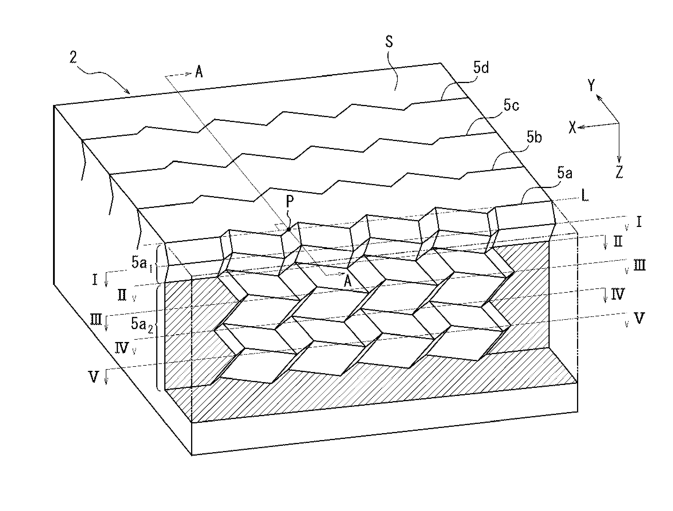
[0047]FIG. 3 is a sectional perspective view of the sipe 5a illustrated in FIG. 2 pertaining to one example of a state in the depth direction.

[0048]As described above, the sipe 5a has a zigzag pattern with amplitude f in a plan view on the land portion surface S. In the depth direction (direction Z) extending from the land portion surface S toward the inner side in the tire radial direction, the sipe 5a is bent and extends while being displaced in the tire circumferential direction (direction Y) and in the tire width direction (direction X). Specifically, the sipe 5a is bent while being displaced in the tire circumferential direction (direction Y) in the vicinity of the land portion surface. The sipe 5a is also bent and extends while being displaced in the tire width direction (direction X) in a region at a greater depth than the vicinity of the land portion surface. In this regard, the sipe 5a extends in the tire radial direction while maintaining the same pattern as the zigzag pat...

second embodiment

[0058]FIG. 5 is a sectional perspective view of the sipe 5a illustrated in FIG. 2 pertaining to another example of a state in the depth direction.

[0059]The sipe 5a has a zigzag pattern with amplitude f on the land portion surface S. In the depth direction (direction Z) extending from the land portion surface S toward the inner side in the tire radial direction, the sipe 5 is bent and extends while being displaced in the tire circumferential direction (direction Y). In this case, the sipe 5a extends in the tire radial direction while maintaining the same pattern as the zigzag pattern present on the land portion surface S.

[0060]Although FIG. 5 illustrates a sectional appearance of, in particular, the sipe 5a among the plurality of sipe 5 illustrated in FIG. 2, in the illustrated example the sipes 5a-5d are arranged parallel to each other and have the identical pattern.

[0061]Next, reference is made to FIG. 6 which is an arrow view of the land portion 2 illustrated in FIG. 5 taken along...

example 1

[0108]Next, Example tires 1-6 according to the present invention, Conventional Example tire according to the conventional technology, and Comparative Example tire 1 were experimentally produced, and each tire was subjected to evaluation of snow performance, dry performance, and wet performance.

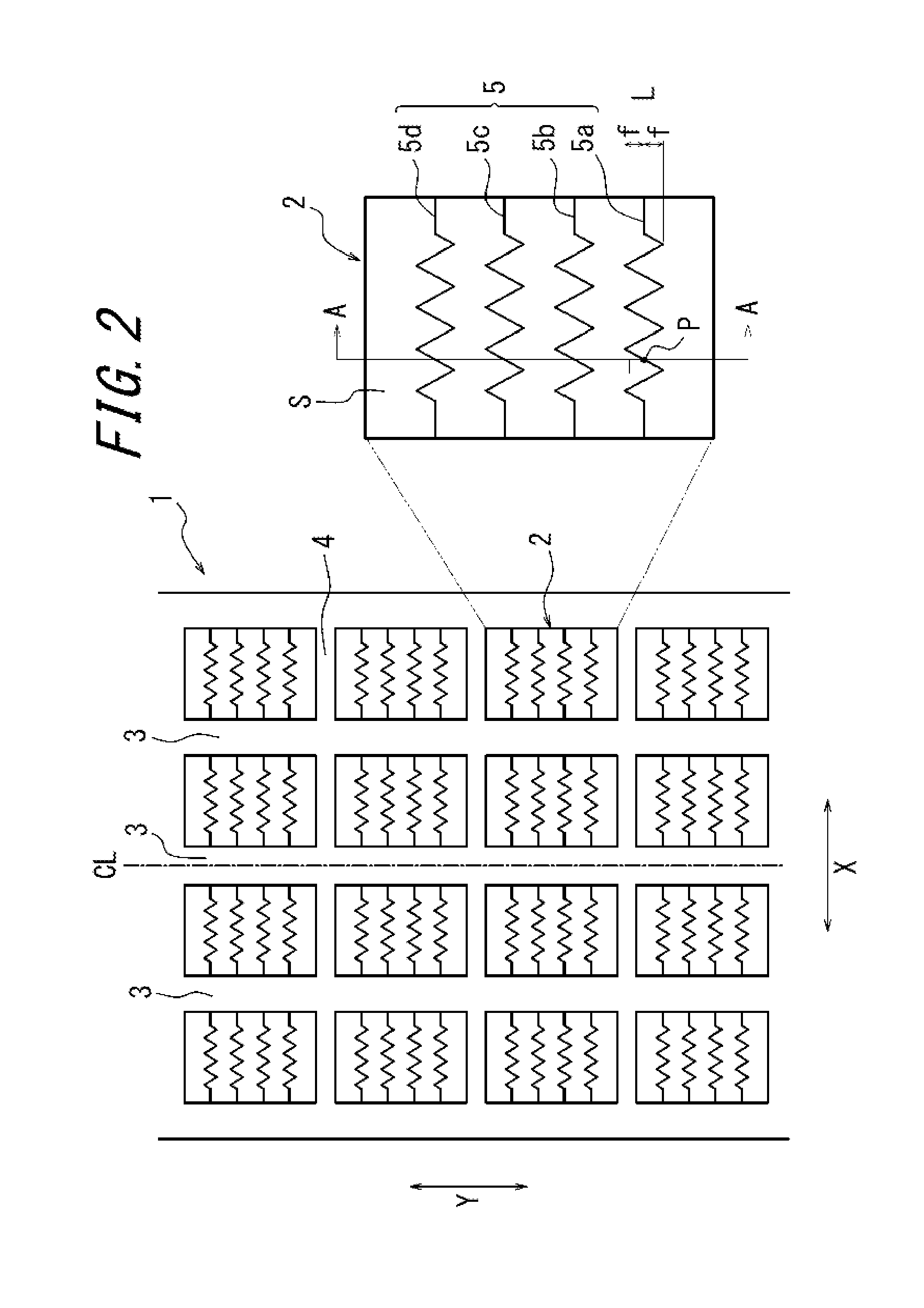
[0109]Example tire 1 is a radial tire for passenger vehicles according to the first embodiment that has a size of 195 / 65R15, an application rim of 6 J×15, and an application internal pressure of 200 kPa and that includes the tread pattern as illustrated in FIG. 2 and a land portion with the sipe section illustrated in FIG. 3 and the sipe center surface 8 illustrated in FIG. 4. Specifications of Example tire 1 are shown in Table 1 below.

[0110]Example tire 2 is a radial tire for passenger vehicles according to the second embodiment that includes the tread pattern as illustrated in FIG. 2 and a land portion with the sipe section illustrated in FIG. 5 and the sipe center surface 8 illustrated in F...


PUM


Abstract

Provided is a pneumatic tire including a land portion provided with a sipe, which is capable of simultaneously providing snow performance, dry performance, and wet performance all at high level in a single land portion. The pneumatic tire includes a land portion 2 on a tread portion. The land portion 2 is provided with a sipe 5 having amplitude in a tire circumferential direction and extending in a tire width direction. In a depth direction extending from a land portion surface S toward an inner side in a tire radial direction, sipe 5 includes: a land portion's surface-side part 5a1 bent toward tire circumferential direction from land portion surface S; and a land portion's bottom-side part 5a2 bent in a direction different from a direction of land portion's surface-side part 5a1 or bent toward tire circumferential direction by a displacement different from a displacement of land portion's surface-side part 5a1.

Description

TECHNICAL FIELD[0001]The present invention relates to a pneumatic tire including a land portion on a tread portion, the land portion being provided with a sipe that has amplitude in a tire circumferential direction and that extends in a tire width direction. The present invention in particular relates to a pneumatic tire capable of simultaneously providing snow performance, dry performance, and wet performance all at a high level.BACKGROUND ART[0002]In order to improve braking performance and traction performance on a snowy road, a tire used for driving on the snowy road has conventionally been provided, in a land portion defined on a tread portion, with a plurality of sipes extending in a tire width direction so as to form edge components. One example of such a sipe is a two-dimensional sipe that has a zigzag or a wave pattern on a tread surface and that is configured by an incision extending vertically relative to the tread surface with the pattern remaining unchanged in a depth d...

Claims


Application Information

Patent Timeline
Patent Type & Authority Applications(United States)
IPC IPC(8): B60C11/12
CPCB60C11/1263B60C11/1218B60C11/0306B60C2011/1213B60C2011/1227
Inventor KAJI, YOSHIO
Owner BRIDGESTONE CORP
Why Eureka
Try Eureka