

Optical acoustic panel
a technology of optical acoustic panels and acoustic panels, which is applied in the direction of lighting elements, lighting and heating apparatuses, instruments, etc., to achieve the effects of preventing too much glare, facilitating efficient manufacturing, and facilitating the manufacture of acoustic panels
- Summary
- Abstract
- Description
- Claims
- Application Information
AI Technical Summary
Benefits of technology
Problems solved by technology
Method used
Image

Examples
Embodiment Construction
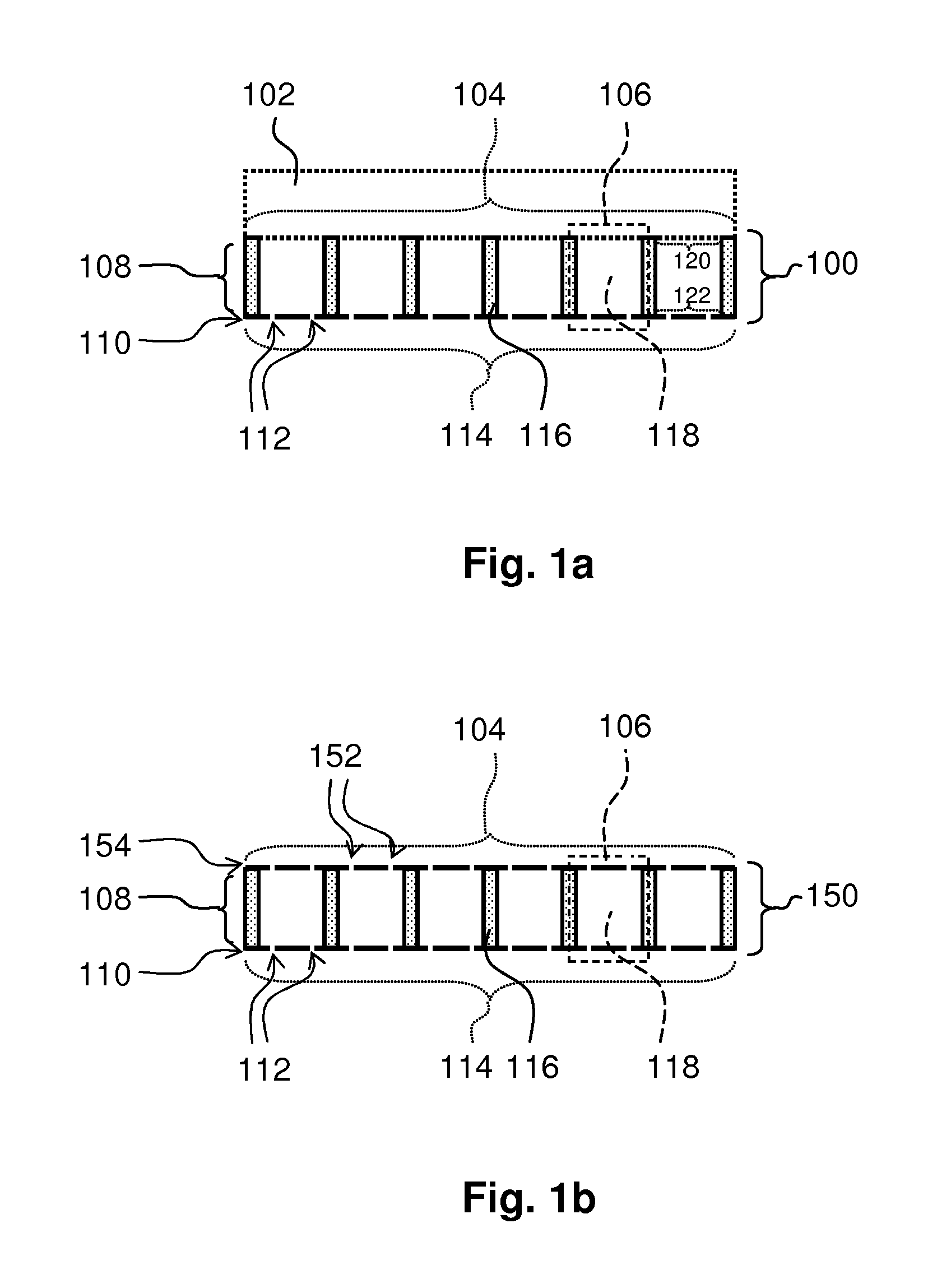
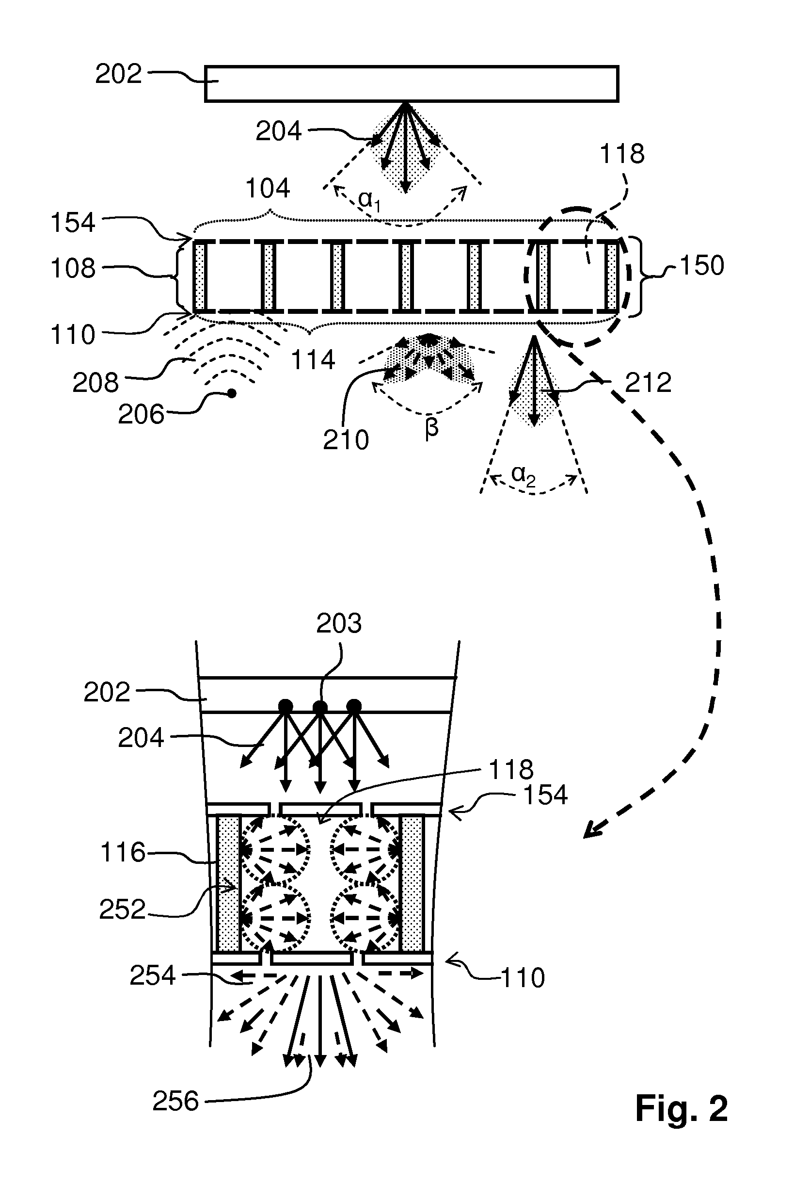
[0047]A first embodiment is shown in FIG. 1a. FIG. 1a schematically shows a cross-section of an embodiment of the optical acoustic panel 100 according to the first aspect of the invention. The optical acoustic panel 100 comprises a spacing structure 108 and a first micro perforated foil 110. The optical acoustic panel 100 has the first micro perforated foil 110 arranged at a first side 114 of the optical acoustic panel 100.
[0048]At a second side 104, being opposite the first side and being arranged parallel to the first side, the optical acoustic panel 100 is configured to be coupled to a means 102 which comprises a surface for closing a cavity between the first side and the surface. The means 102 is drawn schematically and may be a light source, a luminaire, or a transparent plate. A specific surface of the means 102 close the cavity, for example, the surface which is directly applied to the second side 104 of the optical acoustic panel 100, but, if the means does not have a surfac...
PUM
 Abstract
Description
Claims
Application Information