
Upper frame position holding structure and ambulance vibration-proof rack having upper frame position holding structure

a technology of lifting structure and holding structure, which is applied in the direction of mechanical equipment, transportation and packaging, transportation items, etc., can solve the problems of difficult locking and easy lifting, and achieve the effect of easy lifting of the upper frame, effective alleviation and high

Inactive Publication Date: 2014-10-09
DELTA TOOLING CO LTD
View PDF10 Cites 1 Cited by
  • Summary
  • Abstract
  • Description
  • Claims
  • Application Information

AI Technical Summary

Benefits of technology

The present invention concerns an upper frame position holding structure and an ambulance vibration-proof rack. The upper frame position holding structure can force the upper frame to be held in a substantially horizontal posture at any position in its movement trajectory. This makes it easy to perform treatments and operations, such as cardiac massage and loading / unloading of a stretcher, while the rack prevents vibration and nose dive during travel. The structure utilizes a half-pendulum motion and includes a front and rear link mechanism control to achieve smooth and efficient operation.

Problems solved by technology

On the other hand, when the sick or wounded placed on a stretcher is given a predetermined treatment such as a cardiac massage, a vibration-proof rack needs to be locked so as not to move, but in the type swinging up and down and back and forth as disclosed in Patent Document 1, the easy locking has been difficult.

Method used


Image

  • Upper frame position holding structure and ambulance vibration-proof rack having upper frame position holding structure
  • Upper frame position holding structure and ambulance vibration-proof rack having upper frame position holding structure
  • Upper frame position holding structure and ambulance vibration-proof rack having upper frame position holding structure

Examples


Embodiment Construction

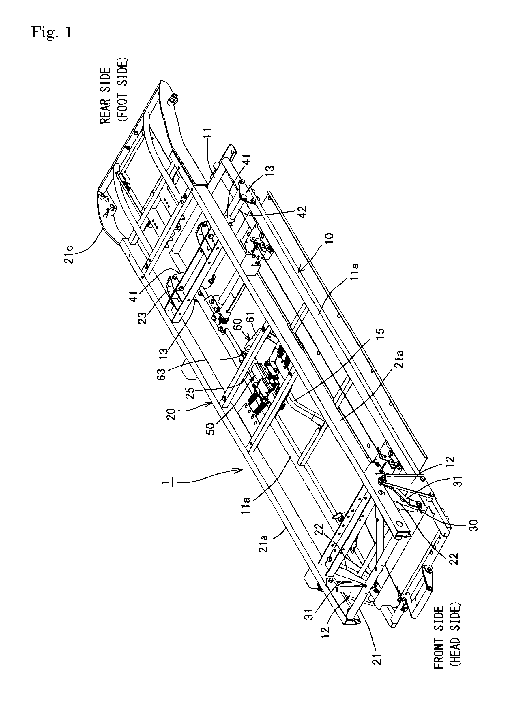
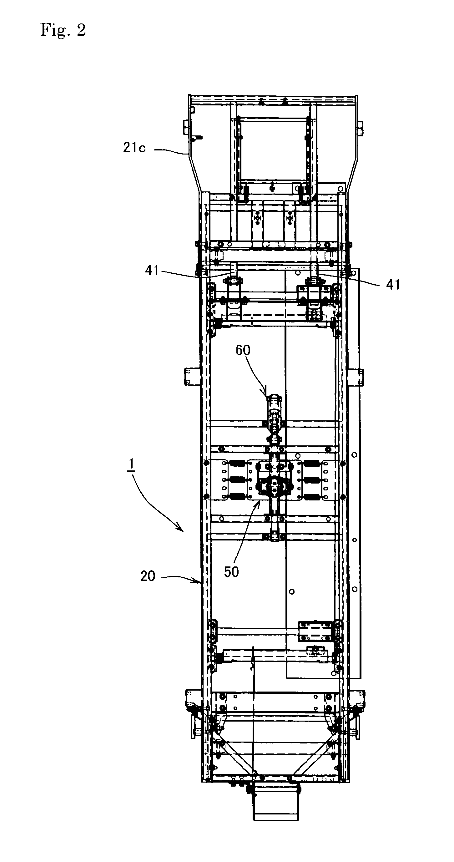
[0045]Hereinafter, the present invention will be described in more detail based on an embodiment illustrated in the drawings. First, based on FIG. 1 to FIG. 6, the basic structure and operation of an ambulance vibration-proof rack 1 to which the upper frame position holding structure of the present invention is applied will be described. The ambulance vibration-proof rack 1 includes a base frame 10 and an upper frame 20.

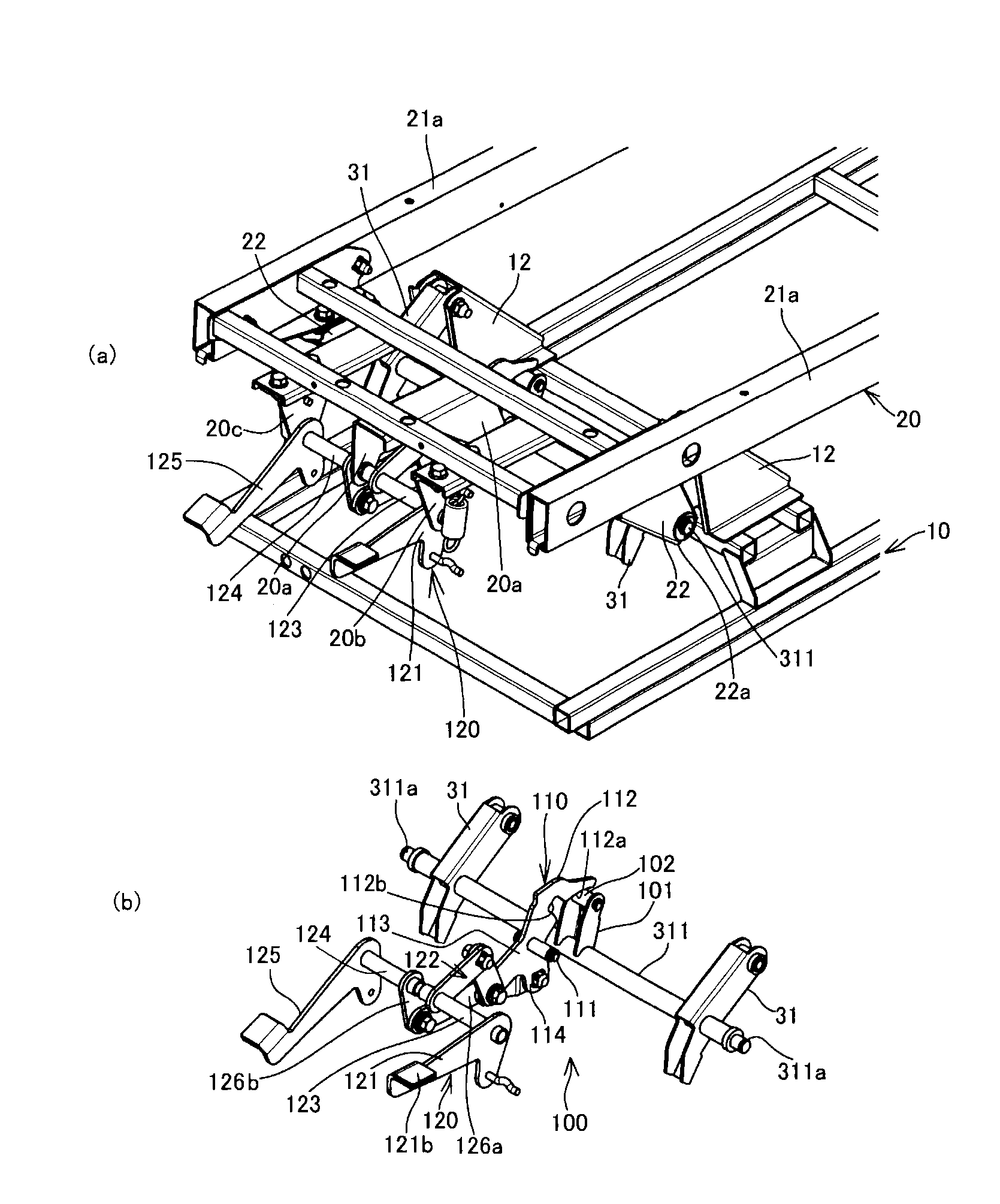
[0046]The base frame 10 has an outer frame member 11 formed in a substantially rectangular shape in a plane view. On front sides (a head side of a person placed on a stretcher) of side frames 11a of the outer frame member 11, base-side front brackets 12 protruding upward are provided. On rear sides (a foot side of the person placed on the stretcher) of the side frames 11a, base-side rear brackets 13 lower in height than the base-side front brackets 12 are provided.

[0047]The upper frame 20 has an outer frame member 21 formed in a substantially rectangular shape in a p...


PUM


Abstract

An upper frame swingable between an inclined posture and a substantially horizontal posture along a trajectory of movement of a four-bar linkage is held in the substantially horizontal posture by a simple operation when necessary. A front link mechanism control gives an external force for pushing down an operation member to thereby control a front link mechanism so as to displace the upper frame rearward while lowering a front side of the upper frame. Since a displacement direction for bringing the upper frame into the substantially horizontal posture and an operation direction for locking the front link mechanism or a rear link mechanism by the operation of the operation member are substantially the same direction, it is possible to perform two movements, the displacement movements to the substantially horizontal posture and the locking movements, only by operating the operation member in a predetermined direction.

Description

TECHNICAL FIELD[0001]The present invention relates to an an upper frame position holding structure which holds an upper frame of an ambulance vibration-proof rack provided in an ambulance to support a stretcher having the sick or wounded thereon and absorbing a vibration and an impact applied to the sick or wounded during the conveyance, in a substantially horizontal posture when necessary, and to an ambulance vibration-proof rack including the upper frame position holding structure.BACKGROUND ART[0002]As an ambulance vibration-proof rack, there has been known, for example, one disclosed in Patent Document 1 proposed by the present applicant. This includes a swingable upper frame provided to lower frames via a link mechanism and swings up and down and back and forth by a vibration transmitted when an ambulance is travelling, owing to a repulsive force of first permanent magnets which are attached to the lower frames and the upper frame, with their repulsive magnetic poles facing eac...

Claims


Application Information

Patent Timeline
Patent Type & Authority Applications(United States)
IPC IPC(8): A61G3/02F16F6/00F16F15/03
CPCA61G3/0254F16F6/005F16F15/03
Inventor OSHIMO, HIROKI
Owner DELTA TOOLING CO LTD
Learn More