
Power monitoring and signal unit

a technology of power monitoring and signal unit, applied in the direction of wireless communication, wireless architecture, instruments, etc., can solve the problems of not being easily integrated with other smart energy control, general use communication equipment,

Inactive Publication Date: 2014-10-09
IMPRENDITORE PTY LTD
View PDF8 Cites 16 Cited by
  • Summary
  • Abstract
  • Description
  • Claims
  • Application Information

AI Technical Summary

Benefits of technology

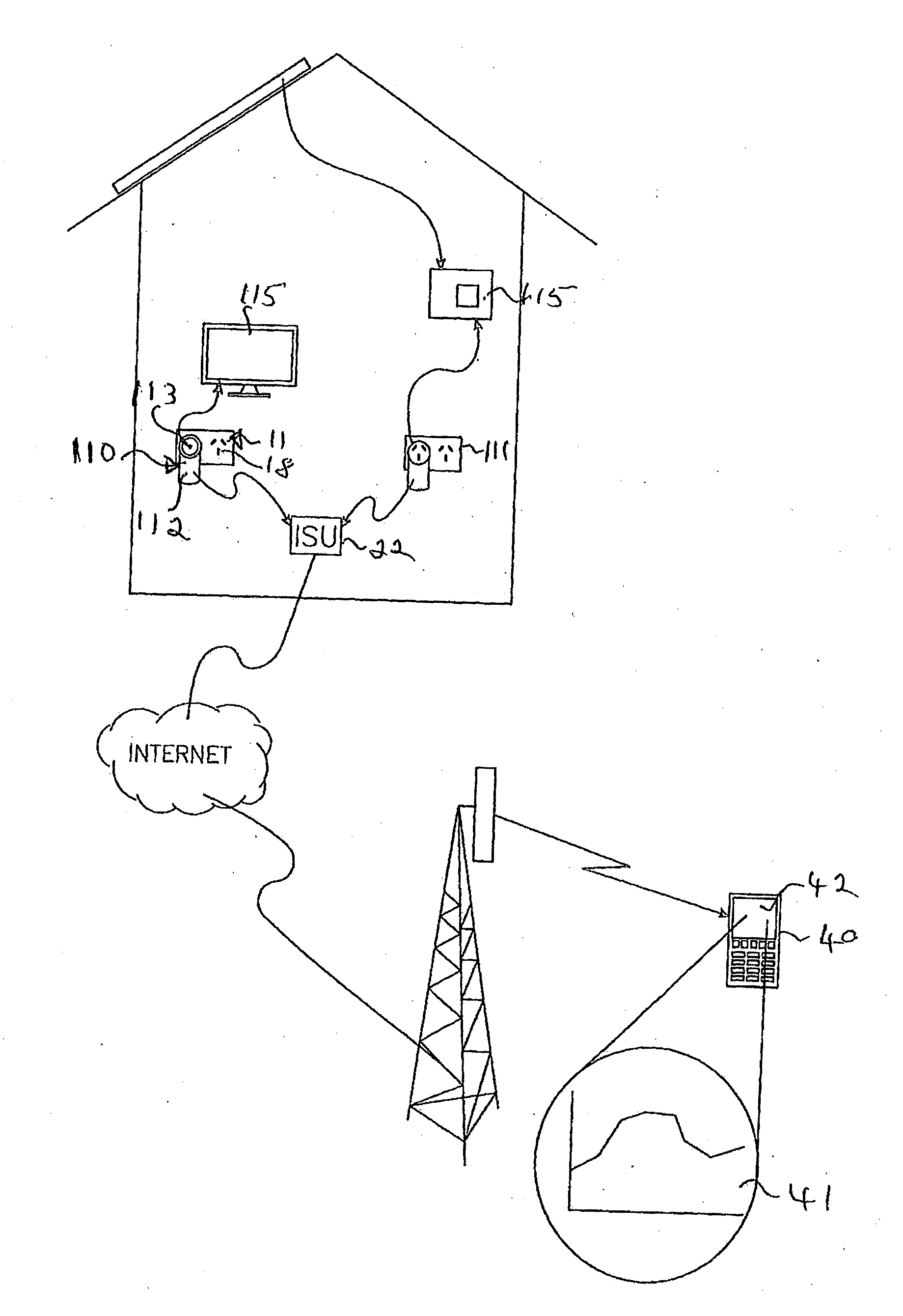
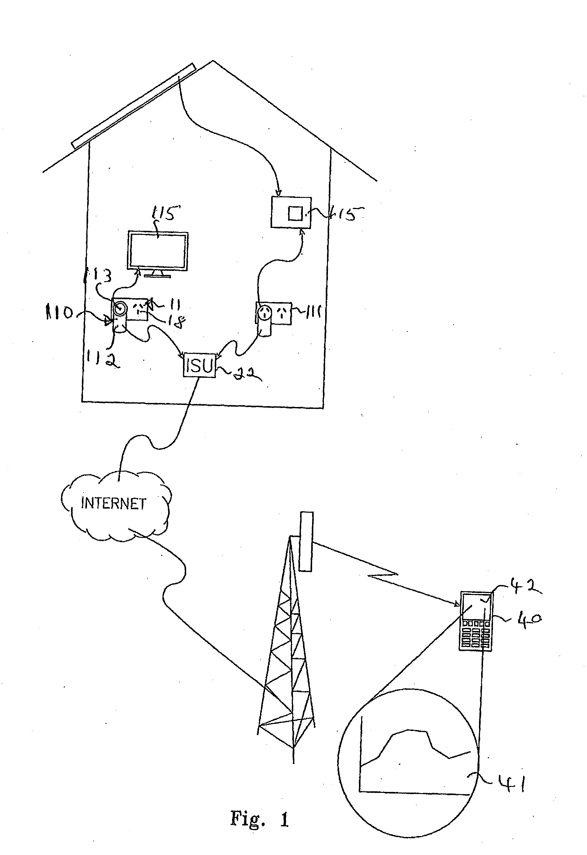
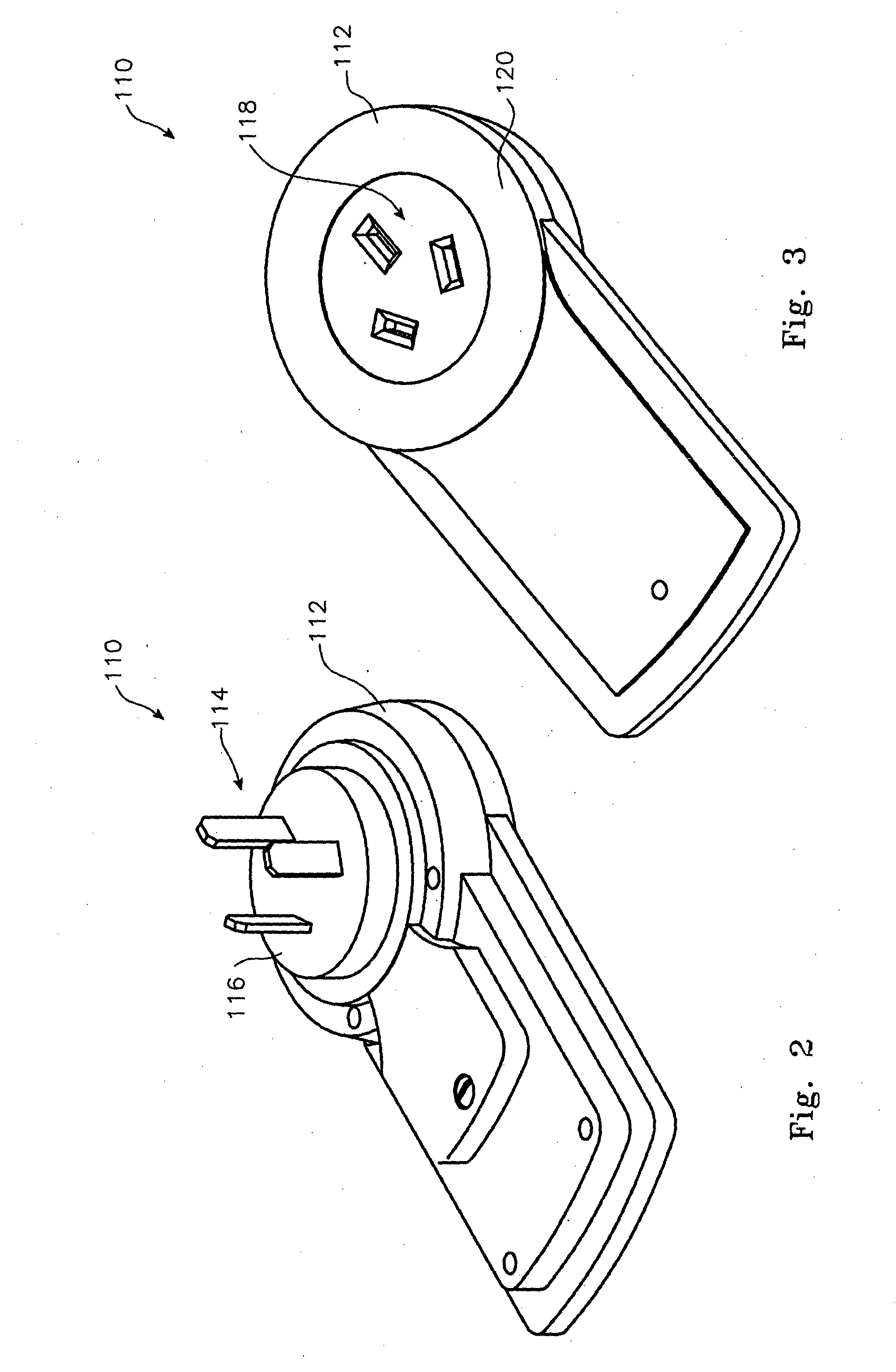
The patent describes a power monitoring and signal unit that can be used in a monitoring system. The unit has projecting connectors for power and can be connected to a mains power outlet. It also has circuitry for monitoring power usage and can transmit data about power usage to a central control facility. The unit can be used in conjunction with other individual signal units registered with the central control facility. The power monitoring and signal unit can be programmed and can be integrated into products as an OEM module. The central control facility can maintain a database and web site for monitoring assets. The technical effects of this patent include improved power monitoring and control for individual or groups of assets in a monitoring system.

Problems solved by technology

The need to conserve electrical power and use it more efficiently has become a pressing social issue as the impact of fossil fuel based generation becomes more widely understood and economies move towards renewable energy sources.
Monitoring devices are known but these generally require specialist installation and, while providing a user with data, are not readily integrated with other smart energy controlling, or general use communication equipment.

Method used


Image

  • Power monitoring and signal unit
  • Power monitoring and signal unit
  • Power monitoring and signal unit

Examples


first preferred embodiment

[0108]With reference to FIG. 9 there is shown a reconfigurable, collaboratively expandable monitoring system 200 in accordance with a first preferred embodiment of the present invention. In this instance the system comprises components as described with reference to Figure (see below). The emphasis in this instance revolves around the reconfigurability and collaborative input of the system 200 whereby third party providers 201 (in this instance, labelled P1, P2, P3 . . . PN) provide respective tools 202 (in this instance, respectively nominated T1, T2, T3 . . . TN), which tools are available for the user / owner / nominated recipient 30 of a respective one or more individual signal units 22 to utilise so as to define steps or actions to occur consequence to events detected and reported by the individual signal units 22. The tools 202 are made available to a user 30 preferably via a web interface screen 203 which will include a tool assembly pane 204 where an individual user 30 can assem...


PUM


Abstract

A power monitoring and signal unit; said unit provided with projecting connectors at a first face and sockets for receiving like connectors in a second opposite face; said unit provided with circuitry for monitoring power flow through said unit when said projecting connectors are plugged into a mains power outlet; said unit further provided with transceiver circuitry for the transmission of data including command and control data and the reception of data including command and control data.In a further form there is disclosed a power monitoring and signal unit in communication with a programmable sensor device; the device comprising an individual signal unit registered by an owner of said individual signal unit with a central control facility;said individual signal unit communicating with said central control facility when and event sensor activates said individual signal unit; said central control facility executing a user-assembled schedule of predefined steps on receipt of a communication from said individual signal unit; said predefined steps configured or reconfigurable by an owner of said individual signal unit from a web site; at least some of the predefined steps provided by one or more independent parties and made available for selection on said web site; at least some predefined steps configurable or reconfigurable by said independent third parties; said method comprising permitting said independent parties to provide said steps to said central control facility via said web site; permitting said owner to register with said central control facility via said web site so as to become a registered owner; permitting said registered owner to select one or more said steps via said web site for execution by said central control facility responsive to communication received from said individual signal unit.

Description

[0001]The present invention relates to control and monitoring of electrical and electronic devices and, more particularly, to intelligent power monitoring and signal transmitting and receiving devices.BACKGROUND[0002]The need to conserve electrical power and use it more efficiently has become a pressing social issue as the impact of fossil fuel based generation becomes more widely understood and economies move towards renewable energy sources.[0003]Energy conservation and use efficiency requires accurate power use monitoring and appropriate action based upon the monitored data. Monitoring devices are known but these generally require specialist installation and, while providing a user with data, are not readily integrated with other smart energy controlling, or general use communication equipment.[0004]It is an object of the present invention to address or at least ameliorate some of the above disadvantages.Notes[0005]1. The term “comprising” (and grammatical variations thereof) is ...

Claims


Application Information

Patent Timeline
Patent Type & Authority Applications(United States)
IPC IPC(8): G01D4/00H04W4/80
CPCG01D4/002H04Q9/00H04Q2209/43G08C17/02G08C2201/93G01R22/063Y04S10/30H04W4/80G01R21/133H02J13/00002Y02E60/00H04W84/12H04W88/02
Inventor RICE, PATRICK JEREMY
Owner IMPRENDITORE PTY LTD
Learn More