

Display apparatus and illumination unit
a technology of illumination unit and display apparatus, which is applied in the direction of lighting and heating apparatus, static indicating devices, instruments, etc., can solve the problems of reducing the luminance of display, and achieve the effect of increasing the light amount and high luminance in the display imag
Active Publication Date: 2014-10-09
SONY CORP
View PDF9 Cites 36 Cited by
- Summary
- Abstract
- Description
- Claims
- Application Information
AI Technical Summary
Benefits of technology
The patent text describes a display apparatus that can switch between three-dimensional and two-dimensional display modes without using physical barriers or polarizers. The apparatus includes a light modulation layer that can scatter light or allow it to pass through in response to an electric field. In three-dimensional display mode, multiple linear lights are emitted, while in two-dimensional display mode, planar light is emitted. The apparatus also includes a lens sheet that narrows the divergence angle of the illumination light, resulting in an increased amount of light that enters the display panel at an appropriate viewing angle. This results in a high luminance in the displayed image.
Problems solved by technology
Therefore, there has been an issue that the polarizer absorbs light, and accordingly, display luminance is decreased.
Method used
View moreImage
Smart ImageViewing Examples

Examples
first embodiment (
1. First Embodiment (Illumination Unit)
[0097]An example in which a lens sheet having a triangular cross-section is provided on a light guide plate
second embodiment (
2. Second Embodiment (Illumination Unit)
[0098]An example in which a lens sheet having a cylindrical cross-section is provided on the light guide plate
3. Modifications of Above-described Respective Embodiments (Illumination Unit)
4. Third Embodiment (Receiver-side Unit)
[0099]An example in which the above-described illumination unit is used as a backlight of a receiver-side unit
Login to View More PUM
| Property | Measurement | Unit |
|---|---|---|
| base angle | aaaaa | aaaaa |
| temperature | aaaaa | aaaaa |
| size | aaaaa | aaaaa |
Abstract
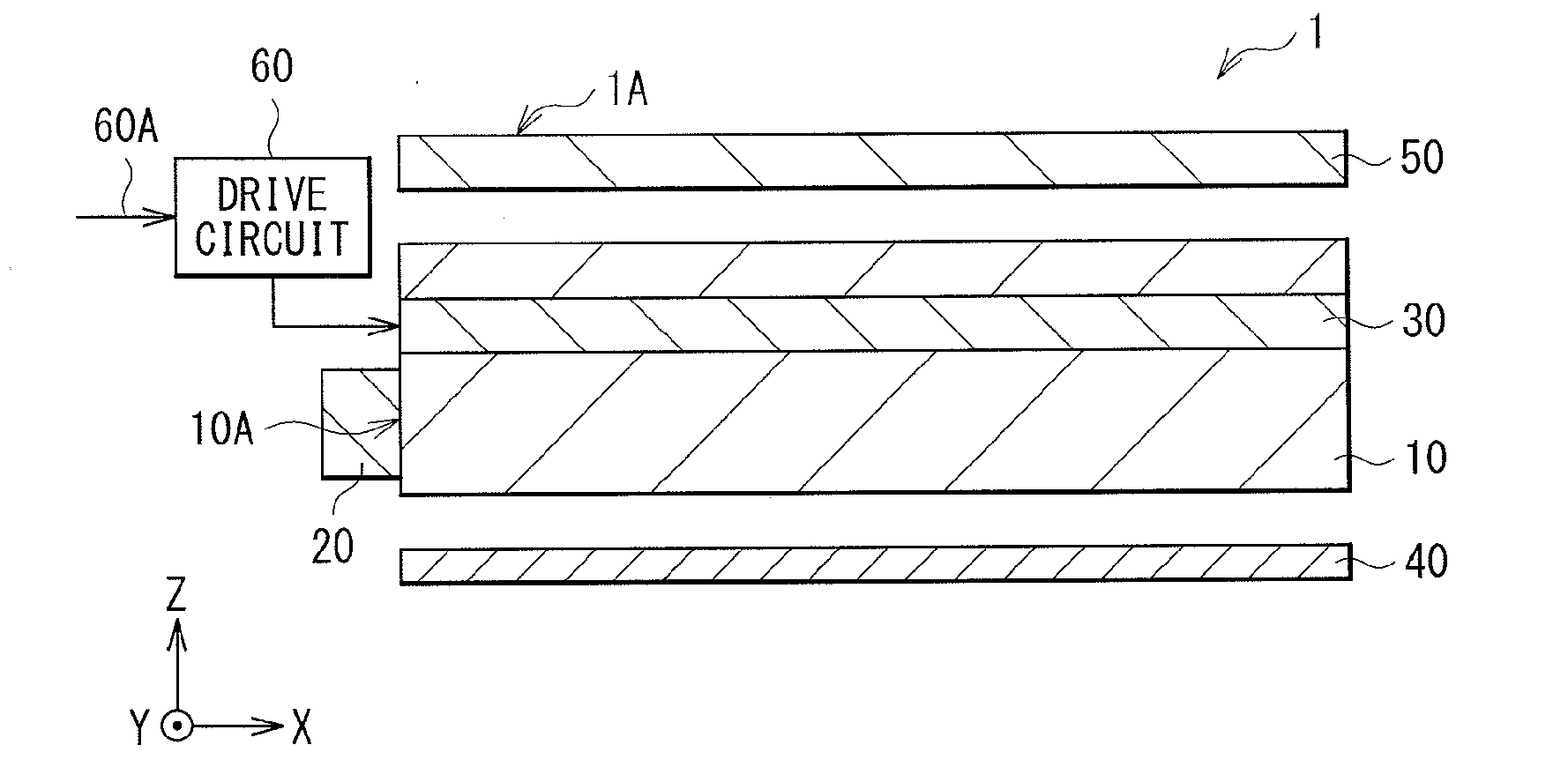
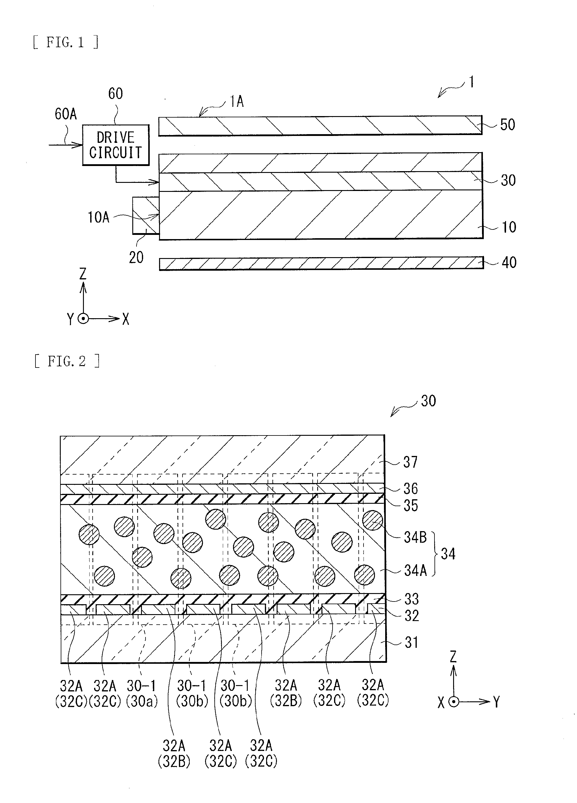
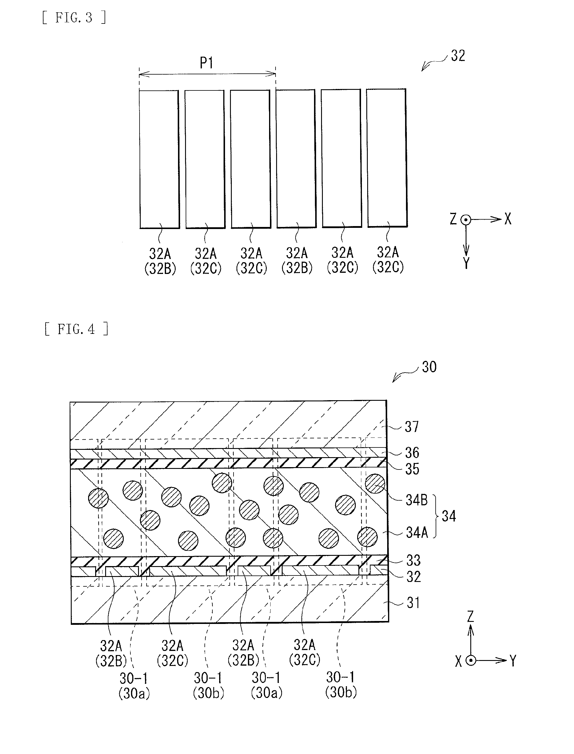
An illumination unit capable of obtaining high luminance and a display apparatus including it are provided. The illumination unit includes an illumination optical system generating the illumination light, and a lens sheet narrowing a divergence angle of the illumination light. The illumination optical system includes a first transparent substrate and a second transparent substrate that are separated from each other and are arranged to face each other, and a light source applying light to an end face of the first transparent substrate or of the second transparent substrate. The illumination optical system is provided in a gap between the first transparent substrate and the second transparent substrate, and includes a light modulation layer exhibiting scattering characteristics or transparent characteristics with respect to the light from the light source in accordance with a magnitude of an electric field. The illumination optical system includes an electrode generating an electric field that generates a plurality of linear scattering regions in the light modulation layer in a three-dimensional display mode, and generating an electric filed that generates a planar scattering region in the light modulation layer in a two-dimensional display mode.
Description
TECHNICAL FIELD[0001]The present technology relates to a display apparatus capable of performing two-dimensional display (planar display) and three-dimensional display (stereoscopic display), and to an illumination unit favorably applicable as a backlight of such a display apparatus.BACKGROUND ART[0002]In some display apparatuses capable of performing three-dimensional display, it is necessary to wear dedicated glasses. In other display apparatuses capable of performing three-dimensional display, it is not necessary to wear dedicated glasses. In the latter display apparatuses, in order to visually recognize a stereoscopic image with naked eyes, a lenticular lens, a parallax barrier, or the like is used. They allow image information to be separately supplied to respective right and left eyes. Therefore, the right and left eyes see different images from each other. As a result, three-dimensional display is achieved.[0003]By the way, in the display apparatus that achieves visual recogn...
Claims
Login to View More Application Information
Patent Timeline
 Patent Type & AuthorityApplications(United States)
IPC IPC(8): G02B27/22G02F1/01F21V9/40G02B30/27G02B30/30
CPCG02F1/01G02B27/2214G02F1/1334G02B6/0061G02B6/0053G02B6/0078G02F1/133606G02F1/133615G02F2203/62G02B30/27G02B30/30
InventorEBISUI, AKIRASHINKAI, SHOGOOKUYAMA, KENTAROSATO, HARUMI
OwnerSONY CORP