Vibration exciter

a technology of vibration exciter and pivot motor, which is applied in the direction of mechanical vibration separation, gearing, belt/chain/gearing, etc., can solve the problems of limited maximum torque of pivot motor and large multiplicity of previous known vibration generators, and achieve the effect of increasing the diameter

Inactive Publication Date: 2014-10-16
ABI ANLAGENTECHN BAUMASCHEN INDBEBEDARF
View PDF13 Cites 14 Cited by
  • Summary
  • Abstract
  • Description
  • Claims
  • Application Information

AI Technical Summary

Benefits of technology

[0021]In a further development of the invention, the lance, on the end side, has a head piece that is increased in diameter, with which it is mounted in the flange part. For this purpose, resilient attachment of the lance in the flange is m

Problems solved by technology

The previously known vibration generator has the disadvantage of a great multiplicity of parts.
Furthermore, the

Method used


Image

  • Vibration exciter
  • Vibration exciter
  • Vibration exciter

Examples


Embodiment Construction

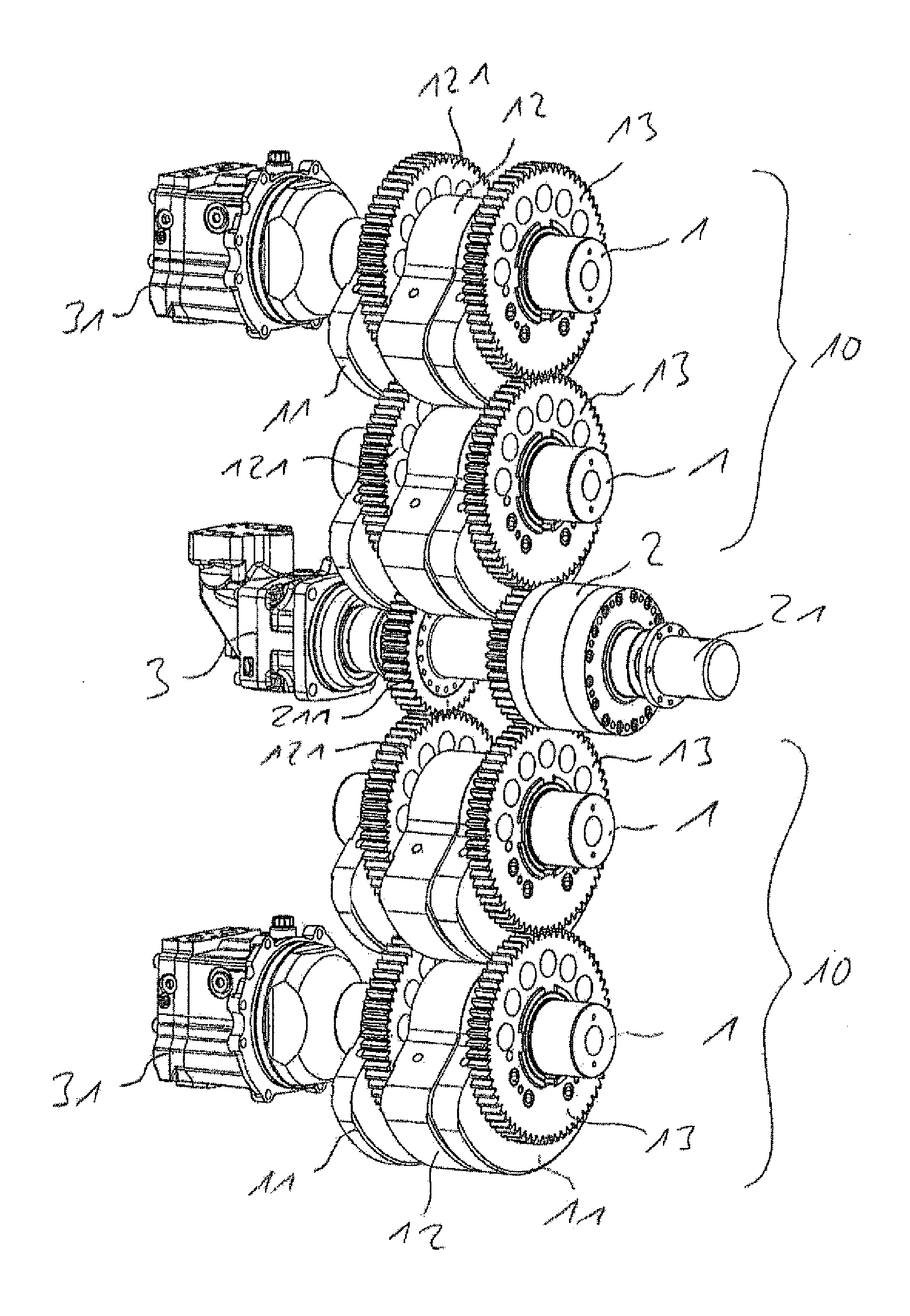
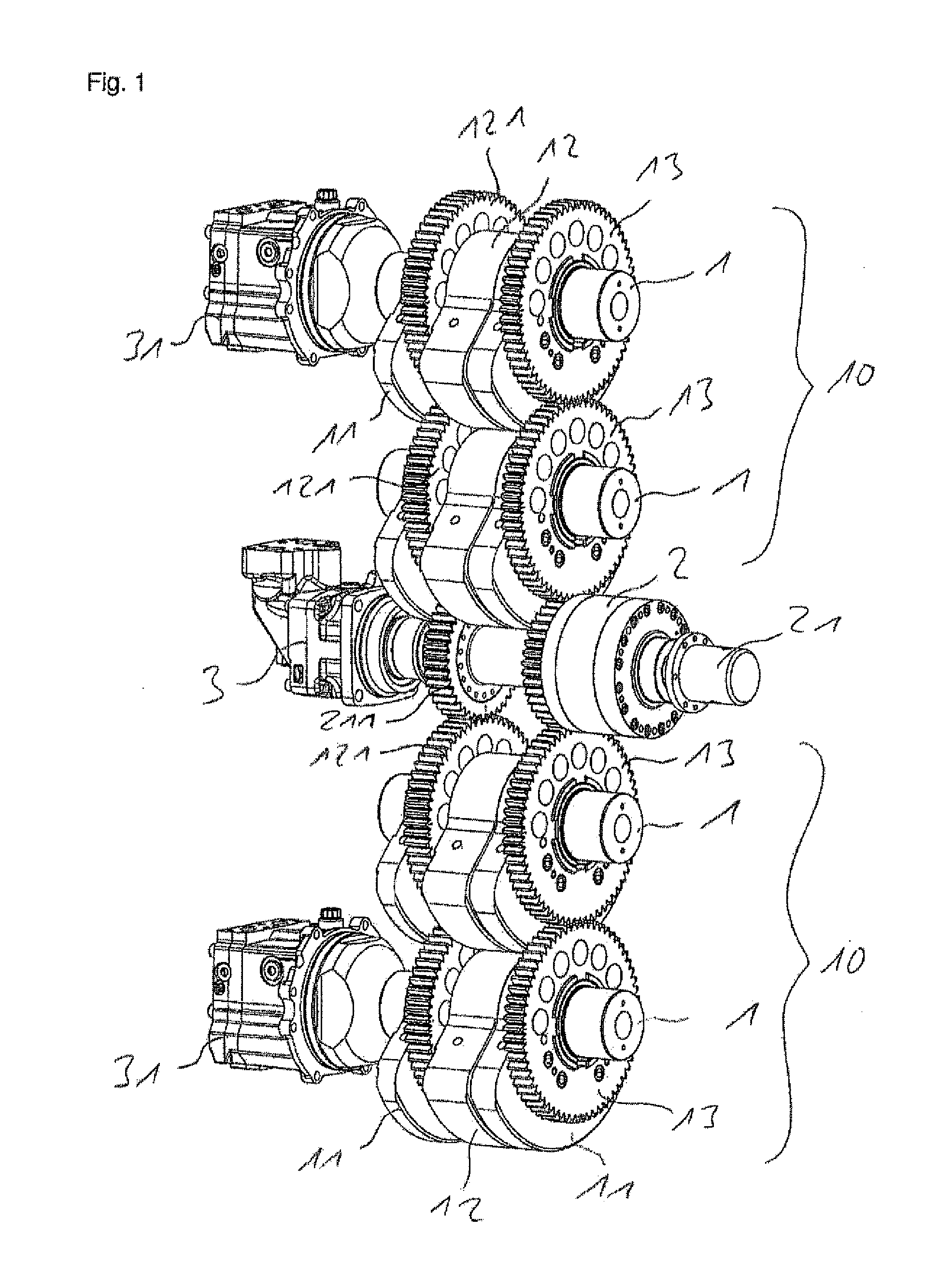
[0028]The vibration exciter selected as an exemplary embodiment is structured as a four-shaft vibrator transmission. Four imbalance shafts 1 are provided, on which two outer imbalance masses 11 are attached at a distance from one another. Centered between the two outer imbalance masses 11, a central imbalance mass 12 is provided, which is connected with a gear wheel 121. Furthermore, a further gear wheel 13 is attached on the imbalance shaft 1, at its end facing the pivot motor 2. The imbalance shafts 1 are disposed parallel to one another, in such a manner that the gear wheels 121, 13 of two imbalance shafts 1, in each instance, stand in engagement with one another, so that two imbalance shaft groups 10 are formed. The two imbalance shaft groups 10 are coupled with one another by way of the gear wheels 211, 221 of a pivot motor 2.

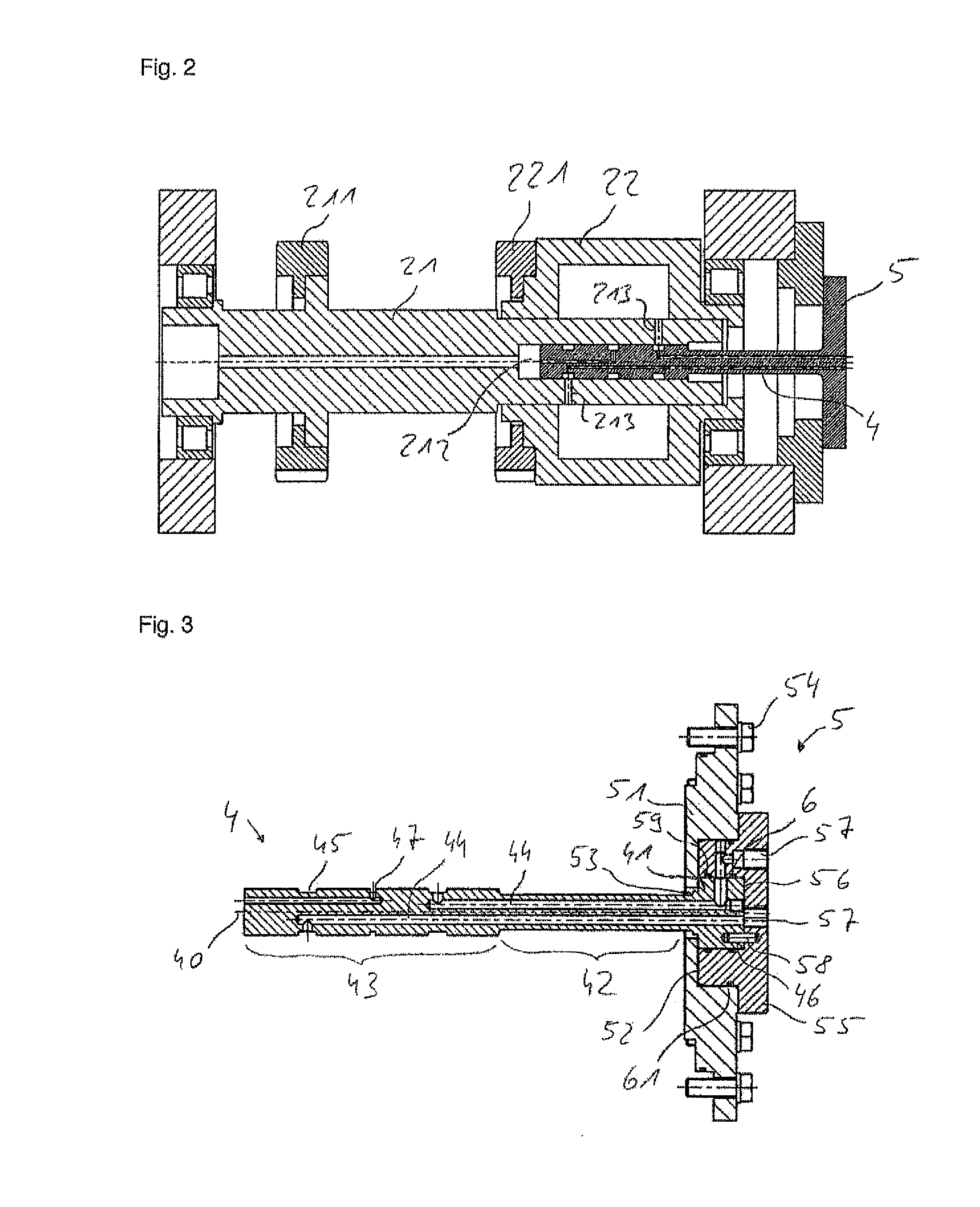
[0029]The pivot motor 2 comprises a pivot motor shaft 21 as well as a pivot motor housing 22, whereby the rotational position of the pivot motor housing 2...


PUM


Abstract

A vibration exciter, particularly for a vibration pile driver, includes at least two shafts disposed parallel to one another, as well as at least two imbalance masses, which are attached on one or more of the shafts. A pivot motor provided for adjustment of the relative rotational position of the imbalance masses with regard to one another, includes a pivot motor shaft and a pivot motor housing. The pivot motor shaft is an integral part of one of the shafts, and the rotational position of the pivot motor housing relative to the pivot motor shaft can be changed. The pivot motor is disposed axially offset, in such a manner that it is disposed outside of the regions through which the imbalance masses move.

Description

CROSS REFERENCE TO RELATED APPLICATIONS[0001]Applicant claims priority under 35 U.S.C. §119 of European Application No. 13163222.6 filed Apr. 10, 2013, the disclosure of which is incorporated by reference.BACKGROUND OF THE INVENTION[0002]1. Field of the Invention[0003]The invention relates to a vibration exciter, particularly for a vibration pile driver.[0004]2. Description of the Related Art[0005]In construction, vibration generators such as vibrators, shakers, or vibration bears, are used to introduce profiles into the ground, or to draw them from the ground, or also to compact ground material. The ground is excited using vibration, and thereby achieves a “pseudo-fluid” state. The goods to be driven in can then be pressed into the construction ground using a static top load. The vibration has a linear movement and is generated by rotating imbalances that run in opposite directions, in pairs, within an exciter transmission. Vibration generators are characterized by the installed im...

Claims


Application Information

Patent Timeline
IPC IPC(8): B06B1/16
CPCB06B1/16B06B1/161B06B1/166F15B15/12Y10T74/18344
Inventor KLEIBL, ALBRECHTHEICHEL, CHRISTIAN
Owner ABI ANLAGENTECHN BAUMASCHEN INDBEBEDARF
Why Eureka
Try Eureka