Differential signal transmission cable and multipair differential signal transmission cable

a transmission cable and differential signal technology, applied in the direction of power cables, cables, insulated conductors, etc., can solve the problems of significant deterioration of characteristics, affecting the transmission characteristics, and deteriorating of transmission characteristics, so as to suppress the deterioration of transmission characteristics

Inactive Publication Date: 2014-10-16
HITACHI METALS LTD
View PDF18 Cites 15 Cited by
  • Summary
  • Abstract
  • Description
  • Claims
  • Application Information

AI Technical Summary

Benefits of technology

[0019]The invention is made in view of such circumstances and it is an object of the invention to provide a differential signal transmission cable and a multipair differential signal transmission cable which allows deterioration in transmission characteristics to be suppressed even in the event of differential- and common-mode coupling.
[0047]According to the invention, it is possible to provide a differential signal transmission cable and a multipair differential signal transmission cable which allows deterioration in transmission characteristics to be suppressed even in the event of differential- and common-mode coupling.

Problems solved by technology

However, when mutual coupling from the differential mode to the common mode or from the common mode to the differential (differential- and common-mode coupling (SCD21, SDC21)) occurs, such as when symmetry of the cable structure is lost due to manufacturing variations, there is a problem in that transmission characteristics (skew characteristics of differential signals) deteriorate due to the skew between the differential and common modes.
However, the high-speed differential signal transmission cable 21 in which the outer conductor 25 is formed by longitudinally wrapping the conductive tape is likely to be affected by the skew between the differential and common modes since the in-phase component is transmitted without attenuation and transmission characteristics significantly deteriorate due to the differential- and common-mode coupling.

Method used


Image

  • Differential signal transmission cable and multipair differential signal transmission cable
  • Differential signal transmission cable and multipair differential signal transmission cable

Examples


Embodiment Construction

[0051]An embodiment of the invention will be described below in conjunction with the appended drawings.

Differential Signal Transmission Cable

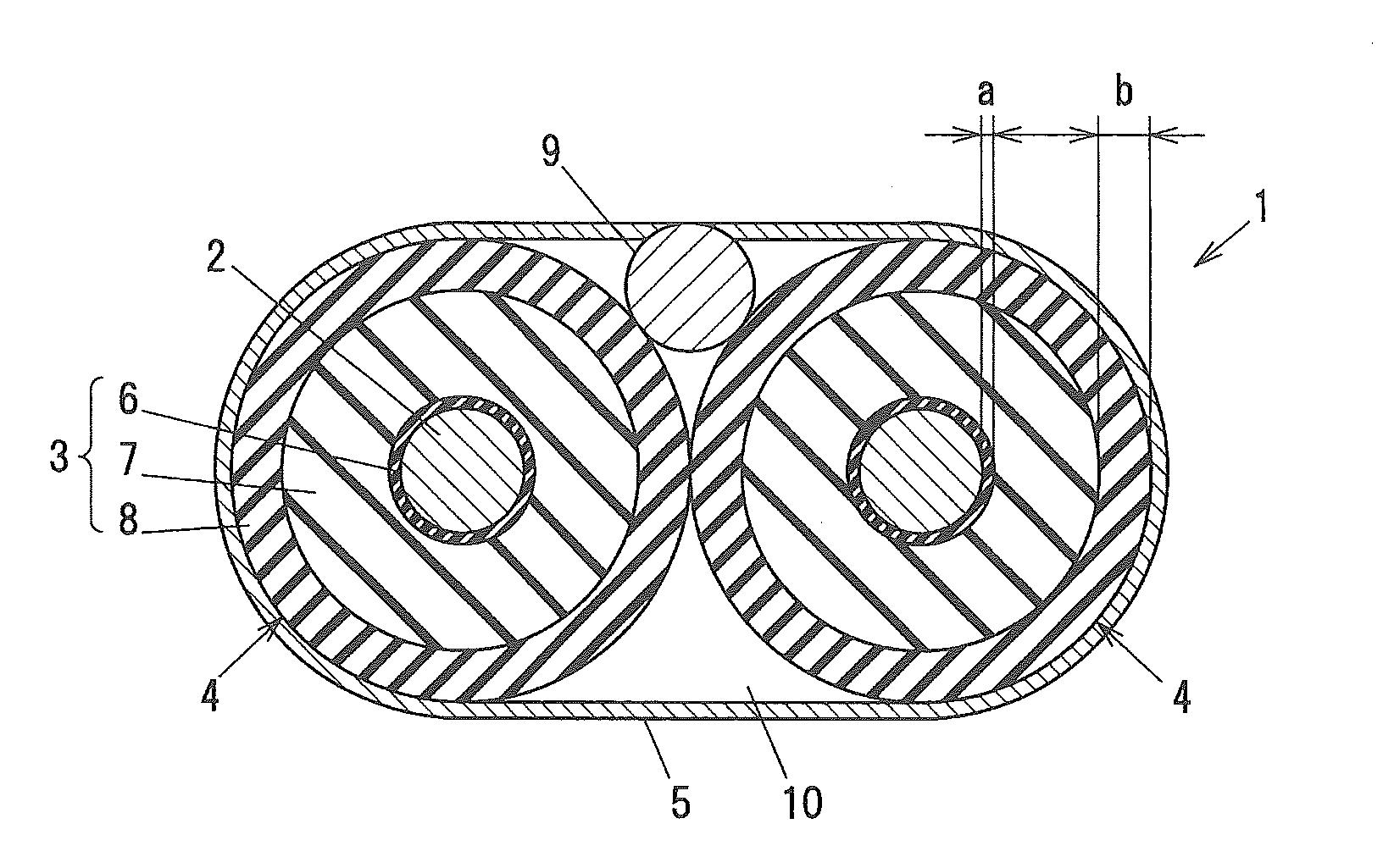
[0052]FIG. 1 is a cross sectional view showing a differential signal transmission cable in the present embodiment.

[0053]As shown in FIG. 1, a differential signal transmission cable 1 is configured such that two core wires 4 each of which comprises an insulation layer 3 on an outer periphery of a conductor 2 are arranged in parallel and an outer conductor 5 is provided so as to cover the two core wires 4 all together.

[0054]The insulation layer 3 is formed by sequentially providing an inner skin layer 6 formed of a non-foamed resin, a foam layer 7 formed of a foamed resin and an outer skin layer 8 formed of a non-foamed resin on the outer periphery of the conductor 2.

[0055]A drain wire 9 for grounding the outer conductor 5 is provided between the two core wires 4 and the outer conductor 5. Note that, the drain wire 9 is not essential and can be ...


PUM

PropertyMeasurementUnit
relative permittivityaaaaaaaaaa
thicknessaaaaaaaaaa
relative permittivityaaaaaaaaaa

Abstract

A differential signal transmission cable includes two core wires arranged in parallel, each of the two core wires having an insulation layer on an outer periphery of a conductor; and an outer conductor provided so as to cover the two core wires all together. The insulation layer includes sequentially an inner skin layer of a non-foamed resin, a foam layer of a foamed resin, and an outer skin layer of a non-foamed resin on the outer periphery of the conductor. The outer skin layer has a higher relative permittivity than the inner skin layer. The multipair differential signal transmission includes a plurality of differential signal transmission cables and a protective jacket provided around the plurality of differential signal transmission cables.

Description

[0001]The present application is based on Japanese Patent Application No. 2013-084834 filed on Apr. 15, 2013, the entire contents of which are incorporated herein by reference.BACKGROUND OF THE INVENTION[0002]1. Field of the Invention[0003]The invention relates to a differential signal transmission cable and a multipair differential signal transmission cable.[0004]2. Description of the Related Art[0005]A differential signal transmission cable 21 as shown in FIG. 2 has been conventionally known.[0006]The conventional differential signal transmission cable 21 shown in FIG. 2 is configured such that two core wires 24 each of which comprises an insulation layer 23 on an outer periphery of a conductor 22 are arranged in parallel and an outer conductor 25 is provided so as to cover the two core wires 24 all together.[0007]When using the insulation layer 23 including a foamed resin layer, the insulation layer 23 further includes generally non-foamed layers called “skin layers” at an inner ...

Claims


Application Information

Patent Timeline
Patent Type & Authority Applications(United States)
IPC IPC(8): H01B11/00H01B7/02
CPCH01B7/02H01B11/002H01B11/1839H01B11/20
Inventor SUGIYAMA, TAKAHIROISHIMATSU, YOSUKENAKAYAMA, AKINARI
Owner HITACHI METALS LTD
Why Eureka
Try Eureka