Broadband antenna and an antenna assembly

a broadband antenna and antenna assembly technology, applied in the direction of antennas, elongated active element feeds, electrically short antennas, etc., can solve the problems of higher assembly defect rate, unsuitable for compact electronics, and greater manufacturing and assembly costs of conventional diversity antennas

Inactive Publication Date: 2014-10-16
QUANTA COMPUTER INC
View PDF4 Cites 7 Cited by
  • Summary
  • Abstract
  • Description
  • Claims
  • Application Information

AI Technical Summary

Benefits of technology

The present invention is about a new type of antenna with adjustable input impedances. It also includes an antenna assembly that has a grounding plane and two broadband antennas. The technical effects of this invention allow for better control over the input of signals and improved performance of the antennas.

Problems solved by technology

The drawbacks of the conventional diversity antenna lie in that, firstly, the input impedances at feed-in points 111, 121 of the first and second radiating components 11, 12 are fixed and cannot be adjusted according to different usage scenarios, and secondly, since the first and second radiating components 11, 12 are separate and non-planar, the conventional diversity antenna has greater manufacturing and assembling costs, higher defect rate due to the need for assembly, and is unsuitable for use in compact electronics, such as universal serial bus (USB) devices.

Method used


Image

  • Broadband antenna and an antenna assembly
  • Broadband antenna and an antenna assembly
  • Broadband antenna and an antenna assembly

Examples


Embodiment Construction

[0020]Before the present invention is described in greater detail, it should be noted that like elements denoted by the same reference numerals throughout the disclosure.

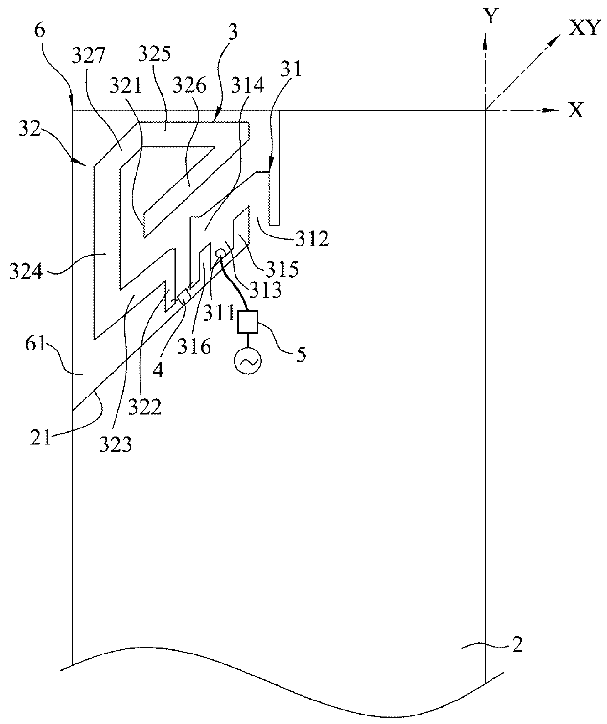
[0021]Referring to FIG. 2, a preferred embodiment of a broadband antenna according to the present invention includes a grounding plane 2, a radiation unit 3, an impedance adjusting unit 4, an input matching unit 5 and a substrate 6.

[0022]The grounding plane 2 provides a reference ground potential and has an edge 21 extending substantially in a first direction (XY).

[0023]The radiation unit 3 includes a first radiation component 31 and a second radiation component 32.

[0024]The first radiation component 31 has a signal feed-in point 311 spaced apart from and disposed adjacent to the edge 21 of the grounding plane 2 for transmitting and receiving a radio frequency (RF) signal, a short circuit arm 312 extending protrudingly from the grounding plane 2, a feeding arm 313 spaced apart from the short circuit arm 312 and havi...


PUM


Abstract

A broadband antenna includes a grounding plane, a radiation unit which has first and second radiation components disposed adjacent to the grounding plane, and an impedance adjusting unit which is operable to adjust an impedance upon receipt of and according to a control signal. A length of a resonance path of the antenna is equal to an overall electrical length of from the first radiation component, the impedance adjusting unit, to the second terminal.

Description

CROSS-REFERENCE TO RELATED APPLICATION[0001]This application claims priority of Taiwanese Application No. 102113451, filed on Apr. 16, 2013.BACKGROUND OF THE INVENTION[0002]1. Field of the Invention[0003]The invention relates to a broadband antenna, more particularly to a broadband antenna with dynamic adjustable impedance inputs.[0004]2. Description of the Related Art[0005]Referring to FIG. 1, a conventional diversity antenna disclosed by U.S. Pat. No. 6,483,463 including a first radiating component 11 and a second radiating component 12 that operate in the same frequency band. The drawbacks of the conventional diversity antenna lie in that, firstly, the input impedances at feed-in points 111, 121 of the first and second radiating components 11, 12 are fixed and cannot be adjusted according to different usage scenarios, and secondly, since the first and second radiating components 11, 12 are separate and non-planar, the conventional diversity antenna has greater manufacturing and a...

Claims


Application Information

Patent Timeline
Patent Type & Authority Applications(United States)
IPC IPC(8): H01Q9/14
CPCH01Q9/145H01Q9/42
Inventor TSAI, CHIN-LUNGTSAI, MEN-HSUEH
Owner QUANTA COMPUTER INC
Why Eureka
Try Eureka