Eureka AIR delivers breakthrough ideas for toughest innovation challenges, trusted by R&D personnel around the world.

Display control method, display apparatus, recording medium, and printing system

Inactive Publication Date: 2014-10-16
SEIKO EPSON CORP
View PDF8 Cites 7 Cited by
  • Summary
  • Abstract
  • Description
  • Claims
  • Application Information

AI Technical Summary

Benefits of technology

The technical effect of this patent is to provide a method and apparatus for controlling the size balance between an attachment position image and a preview image on a display. This allows the user to easily adjust the size balance between the two images and ensure that the label is properly aligned and looks good when printed. Additionally, the patent also allows for changing the preview image into a trapezoid shape to match the distortion of the attachment position image. This makes it easier to confirm the correct size balance between the two images and reduces any unevenness or difficulty during printing.

Problems solved by technology

However, there is a case where the user does not seriously consider a size balance between the attachment position and the label and sets character input, font size, and the like.
As a result, the user does not obtain a good size balance between the attachment position image and the preview image in some cases.
In the printing apparatus of the related art, it is not possible to change a relative size of the preview image with respect to the attachment position image.
For this reason, even in a case where the size balance between the attachment position image and the preview image displayed on the touch panel display portion is not good, unless the character input and the font size are newly set, it is not possible to adjust the size balance between the attachment position image and the preview image.
Therefore, before printing the label, the user is not able to confirm the attached image of which the size balance between the attachment position image and the preview image is adjusted.

Method used


Image

  • Display control method, display apparatus, recording medium, and printing system
  • Display control method, display apparatus, recording medium, and printing system
  • Display control method, display apparatus, recording medium, and printing system

Examples


Embodiment Construction

[0027]Hereinafter, one embodiment of a display control method, a display apparatus, a recording medium, and a printing system according to the invention will be described with reference to the attached drawings.

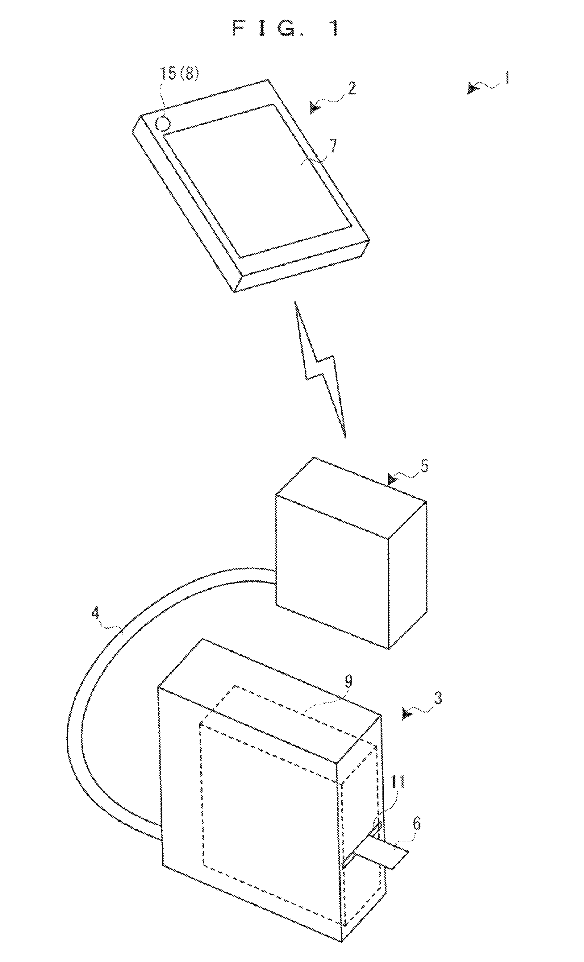
[0028]FIG. 1 is a configuration diagram of a printing system according to an embodiment of the invention.

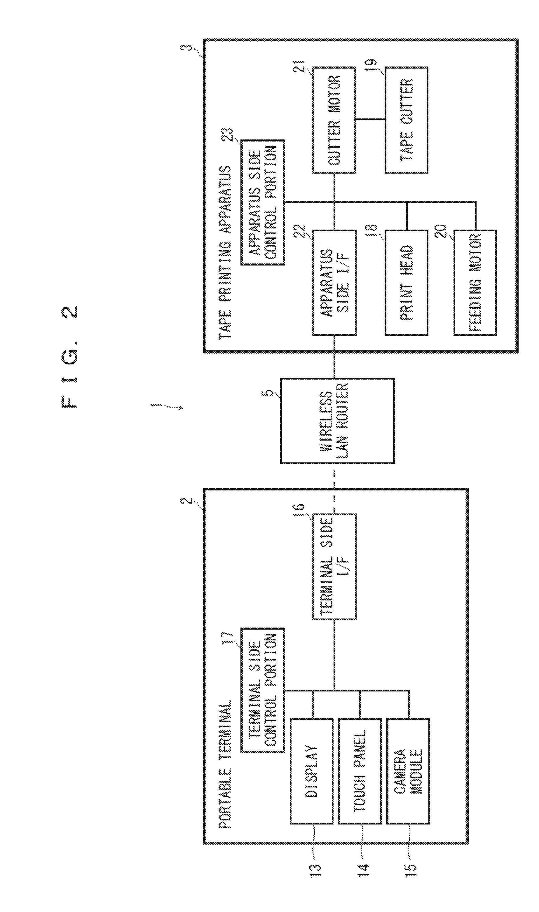
[0029]As shown in FIG. 1, the printing system 1 of the embodiment includes a portable terminal 2 as the display apparatus and a tape printing apparatus 3. The tape printing apparatus 3 is wirelessly connected and able to communicate with the portable terminal 2 through a wireless Local Area Network (LAN) router 5 connected by a Universal Serial Bus (USB) cable 4, for example. That is, the wireless LAN router 5 functions as a print server. The tape printing apparatus 3 and the portable terminal 2 also may be configured to be directly connected in a wireless or wired manner without connecting through the wireless LAN router 5.

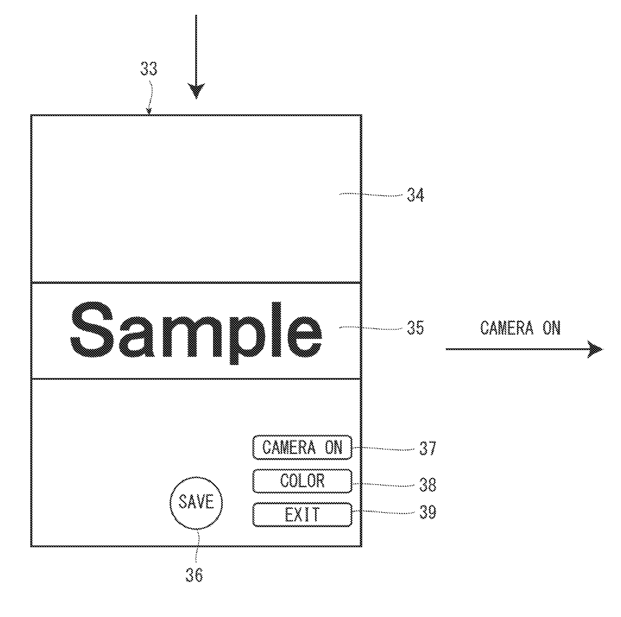
[0030]The portable terminal 2 is installed with a...


PUM


Abstract

Provided is a display control method including: obtaining an attachment position image which is an image of an attachment position to which a label having a printing image printed on a printing medium is attached; generating a preview image of the label on which the printing image is printed; generating a synthesized image obtained by overlapping the attachment position image and the preview image; displaying the synthesized image on a display portion; receiving an operation from a user to change the synthesized image in a state where the synthesized image is displayed on the display portion; and displaying the changed synthesized image on the display portion, based on the operation in the receiving of the operation.

Description

CROSS REFERENCES TO RELATED APPLICATIONS[0001]The entire disclosure of Japanese Patent Application No. 2013-081902, filed Apr. 10, 2013 is expressly incorporated by reference herein.BACKGROUND[0002]1. Technical Field[0003]The present invention relates to a display control program, a display control method, a display apparatus, and a printing system for displaying a synthetic image obtained by overlapping an image of an attachment position image to which a label is attached and a preview image of the label on a display portion.[0004]2. Related Art[0005]In the related art, a printing apparatus that includes a photographing portion and a touch panel display portion that displays an image photographed at the photographing portion, and creates a label by combining an image of an attachment position to which a label is attached with a preview image of the label before printing and by displaying the combined image on the touch panel display portion is known. The printing apparatus displays...

Claims


Application Information

Patent Timeline
IPC IPC(8): G06K15/02
CPCG06K15/024G06K15/025B41J3/4075G06K15/002G06F3/1208G06F3/1256G06F3/1292
Inventor HIRABAYASHI, NAOFUMIKASAHARA, MINORUWATANABE, JUNPEI
Owner SEIKO EPSON CORP
Why Eureka
Eureka Blog
Learn More