Electronic device, image forming apparatus, and control method
- Summary
- Abstract
- Description
- Claims
- Application Information
AI Technical Summary
Benefits of technology
Problems solved by technology
Method used
Image

Examples
first embodiment
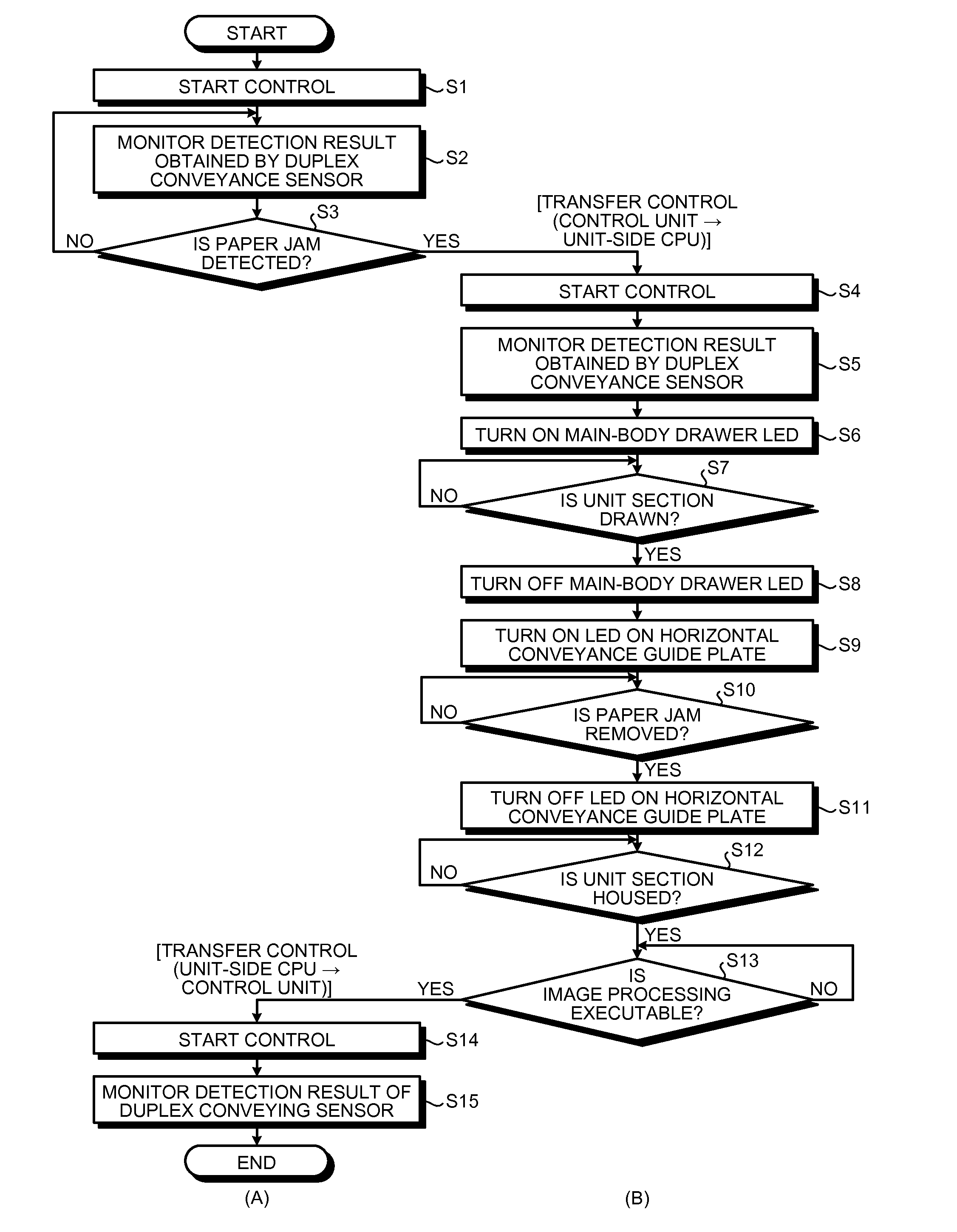
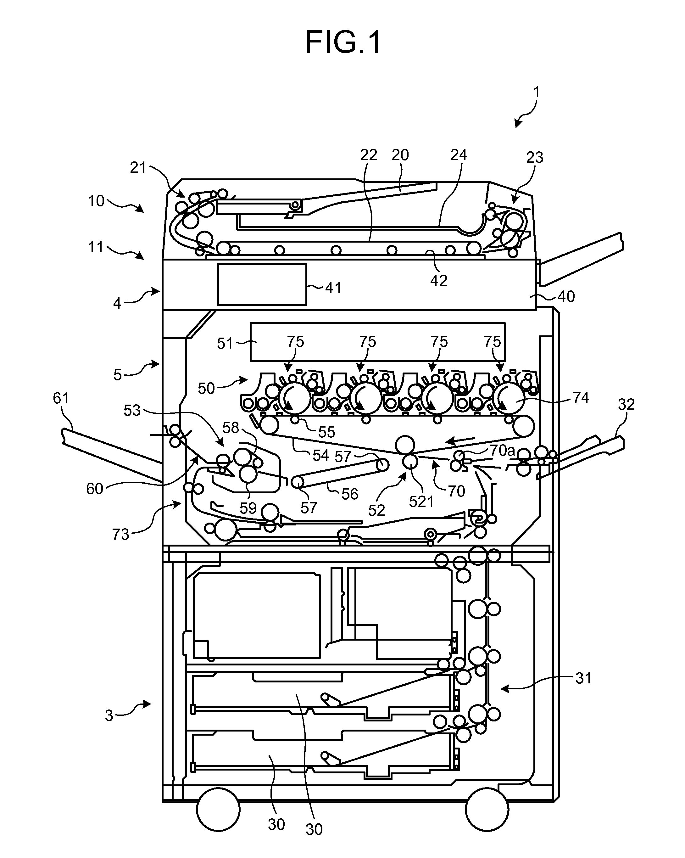
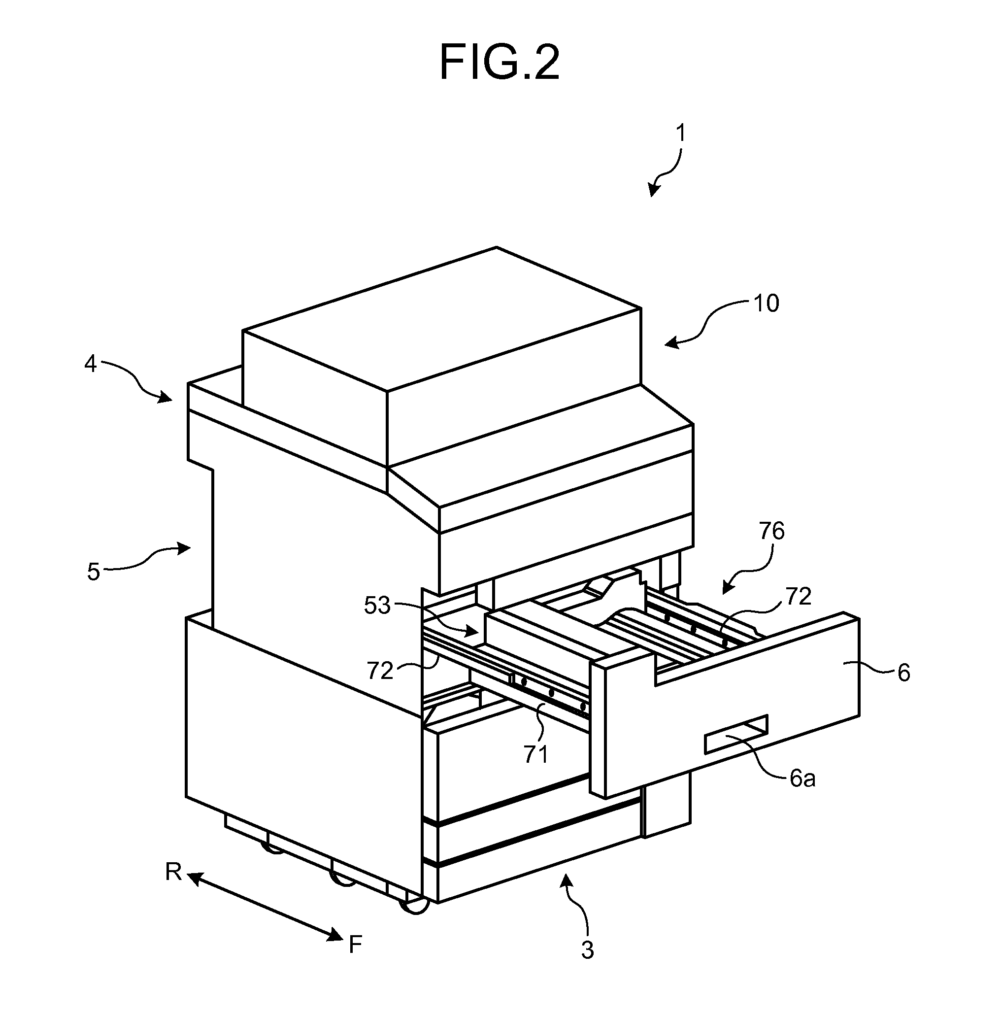
[0027]FIG. 1 is a diagram illustrating a configuration example of an image forming apparatus 1 according to a first embodiment. As illustrated in FIG. 1, the image forming apparatus 1 includes an auto document feeder (ADF) 10 and an apparatus main-body 11. The apparatus main-body 11 includes a sheet feed unit 3, an image reading unit 4, and an apparatus main-body unit 5.
[0028]The ADF 10 includes a document tray 20, a document feed roller 21, a document conveying belt 22, a document discharge roller 23, and a document discharge tray 24. The ADF 10 is attached to the image reading unit 4 via an opening / closing mechanism (not illustrated), such as a hinge, so as to be opened and closed.
[0029]The document feed roller 21 separates each document (not illustrated) from a bundle of documents stacked on the document tray 20, and conveys each document toward the image reading unit 4. The document conveying belt 22 conveys the document separated by the document feed roller 21 to the image read...
second embodiment
[0059]Next, a second embodiment will be explained. The second embodiment differs from the first embodiment in that it includes a wire communication unit that connects, with wires, the control unit 100 and the loads for which the transmission efficiency and the speed are not prioritized (the load 201, the load 202, and the load 203) under the state that the unit section 76 is housed in the apparatus main-body unit 5. Detailed explanation will be given below. Explanation of the same components as those of the first embodiment described above will be omitted appropriately.
[0060]FIG. 8 and FIG. 9 are schematic diagrams illustrating an example of a connection configuration of the control unit 100 and the unit section 76 according to the present embodiment. In the example in FIG. 8 and FIG. 9, the unit section 76 includes a load 206, in addition to the five loads (the load 201 to the load 205) as described above. Furthermore, in this example, wire communication connectors 300 and 310 are ...
first modification
of Second Embodiment
[0071]As illustrated in FIG. 11 and FIG. 12 for example, the wire communication connectors 300 and 310 may connect only the load 201 among the load 201, the load 202, and the load 203 to the control unit 100 with the wires under the state that the unit section 76 is housed in the apparatus main-body unit 5 (see FIG. 11), and disconnect the wire connection between the load 201 and the control unit 100 under the state that the unit section 76 is drawn from the apparatus main-body unit 5 (see FIG. 12).
[0072]Furthermore, in this example, the load 201 is also connected to the serial communication unit 210 similarly to the second embodiment. As illustrated in FIG. 11, under the state that the unit section 76 is housed in the apparatus main-body unit 5, the load 201 connected to the control unit 100 via the wire communication connectors (300 and 310) performs wire communication with the control unit 100 via the wire communication connectors (300 and 310) and does not pe...
PUM
 Abstract
Description
Claims
Application Information
 - Generate Ideas
- Intellectual Property
- Life Sciences
- Materials
- Tech Scout
- Unparalleled Data Quality
- Higher Quality Content
- 60% Fewer Hallucinations
Browse by: Latest US Patents, China's latest patents, Technical Efficacy Thesaurus, Application Domain, Technology Topic, Popular Technical Reports.
© 2025 PatSnap. All rights reserved.Legal|Privacy policy|Modern Slavery Act Transparency Statement|Sitemap|About US| Contact US: help@patsnap.com