Filter array with reduced stray light

a filter array and filter technology, applied in the field of optical filter arts, optical filter arts, spectrographic arts, etc., can solve the problems of difficult or impossible to vary the thickness of the layer across the substrate pla

Active Publication Date: 2014-10-16
MATERION
View PDF6 Cites 26 Cited by
  • Summary
  • Abstract
  • Description
  • Claims
  • Application Information

AI Technical Summary

Problems solved by technology

However, it is difficult or impossible to vary the layer thicknesses across the substrate plate during layer deposition or by post-deposition processing in a controlled manner in order to provide different pass-bands or stop-bands in different areas of the plate.

Method used


Image

  • Filter array with reduced stray light
  • Filter array with reduced stray light
  • Filter array with reduced stray light

Examples


Embodiment Construction

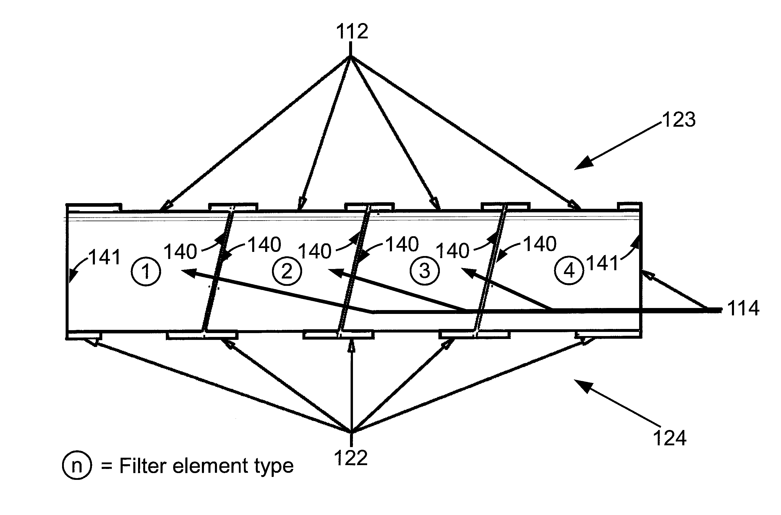
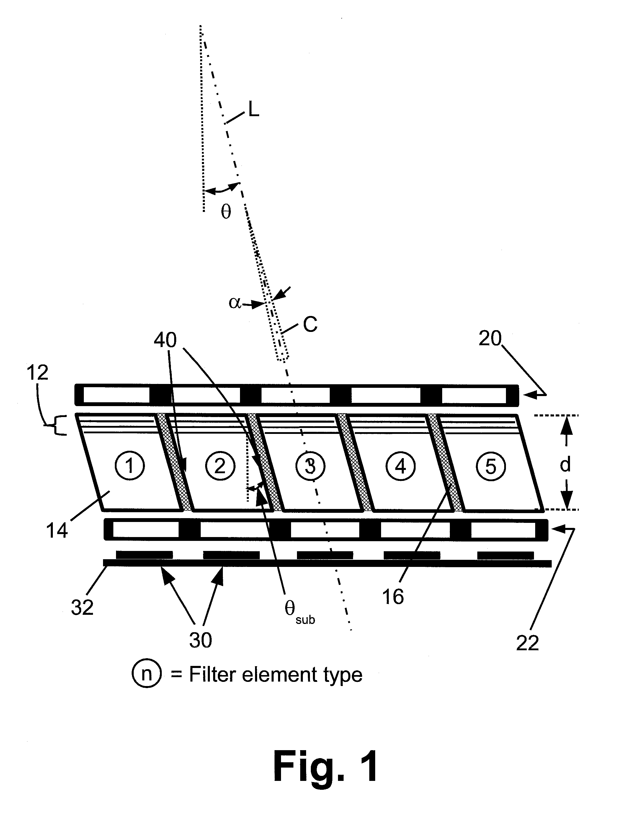
[0015]A disadvantage of filter arrays recognized herein is the possibility of edge effects at the boundaries between adjacent bonded filter elements. This can be reduced by using optically absorbing adhesive, surface roughening, or other control of the interfaces between filter elements so as to avoid stray light leakage at these boundaries.

[0016]However, in some applications the filter array is illuminated at an angle. It is recognized herein that these techniques can be ineffective in this case, because stray light can be generated by total internal reflection (TIR) at the substrate surface and / or by reflection or scattering from the adhesive or other bond.

[0017]Another difficulty recognized herein with angled illumination of a filter array is that the size of the filter elements is increased. This is due to the need to accommodate the shift in light at the exit aperture compared with the entrance aperture due to the angle of light. If the angle of light traveling through the opti...


PUM

PropertyMeasurementUnit
angleaaaaaaaaaa
angleaaaaaaaaaa
refractive indexaaaaaaaaaa

Abstract

Optical filter elements each include a parallelogram-shaped substrate with parallel light entrance and light exit surfaces and parallel slanted sidewalls slanted at an angle, and an interference filter disposed on one or both of the light entrance surface and the light exit surface. The optical filter elements are bonded together at the slanted sidewalls to form the optical filter array. Light is filtered by illuminating the optical filter array at an angle θ equal to or corresponding to the angle of the slanted sidewalls. In some embodiments the angle of the slanted sidewalls corresponds to the angle-of-incidence θ by Snell's law.

Description

[0001]This application claims the benefit of U.S. Provisional Application No. 61 / 812,397 filed Apr. 16, 2013 and titled “FILTER ARRAY WITH REDUCED STRAY LIGHT”. U.S. Provisional Application No. 61 / 812,397 filed Apr. 16, 2013 is incorporated herein by reference in its entiretyBACKGROUND[0002]The following relates to the optical arts, optical filter arts, spectrographic arts, pricing information distribution arts, and related arts.[0003]Optical filters with high spectral selectivity can be manufactured using a stack of layers with alternating layers of two (or more) constituent materials having different refractive index values. Such filters are sometimes called interference filters, and can be designed to provide a designed pass-band, stop-band, high-pass, or low-pass output. For pass-band filters, the width of the pass-band can typically be made as narrow as desired by using more layer periods in the stack, albeit possibly with some transmission loss at the peak transmission wavelen...

Claims


Application Information

Patent Timeline
Patent Type & Authority Applications(United States)
IPC IPC(8): G02B5/28G02B5/20
CPCG02B5/285G02B5/283G02B5/281G02B5/201G02B2207/123G02B27/0018G02B27/28Y10T156/1062
Inventor DOWNING, KEVIN R.TRIBICK, IAN S.
Owner MATERION
Why Eureka
Try Eureka