Manufacturing method and manufacturing device for manufacturing a joined piece

a manufacturing method and technology of joining parts, applied in the direction of computer control, program control, instruments, etc., can solve the problems of inconvenient repositioning or changing out of joints, and achieve the effect of accurate part attachmen

Inactive Publication Date: 2014-10-16
NISSAN MOTOR CO LTD
View PDF10 Cites 27 Cited by
  • Summary
  • Abstract
  • Description
  • Claims
  • Application Information

AI Technical Summary

Benefits of technology

[0011]In accordance with the present invention, an image taken of a second member to be joined to a first member being held at a holding position prior to being joined is compared to a reference image, the deviation amount of the holding position of the second member is determined based on the results of the comparison, the correction amount for the holding position of the second member is determined according to the deviation amount, the position of the second member is corrected according to the correction amount, and the members are joined. It is therefore sufficient to perform manual measurement only once, after which a positional correction amount for the part can be obtained via an image of the second member and image processing alone, allowing for accurate part attachment. This allows for flexible adaptation to changes in part positions or in the parts themselves.

Problems solved by technology

However, if jigs are used to hold parts in place during welding, the jigs must be inconveniently repositioned or changed out for differently shaped jigs when the parts are rearranged or differently shaped parts are used.

Method used


Image

  • Manufacturing method and manufacturing device for manufacturing a joined piece
  • Manufacturing method and manufacturing device for manufacturing a joined piece
  • Manufacturing method and manufacturing device for manufacturing a joined piece

Examples


embodiment

[0096](Alternative Embodiment)

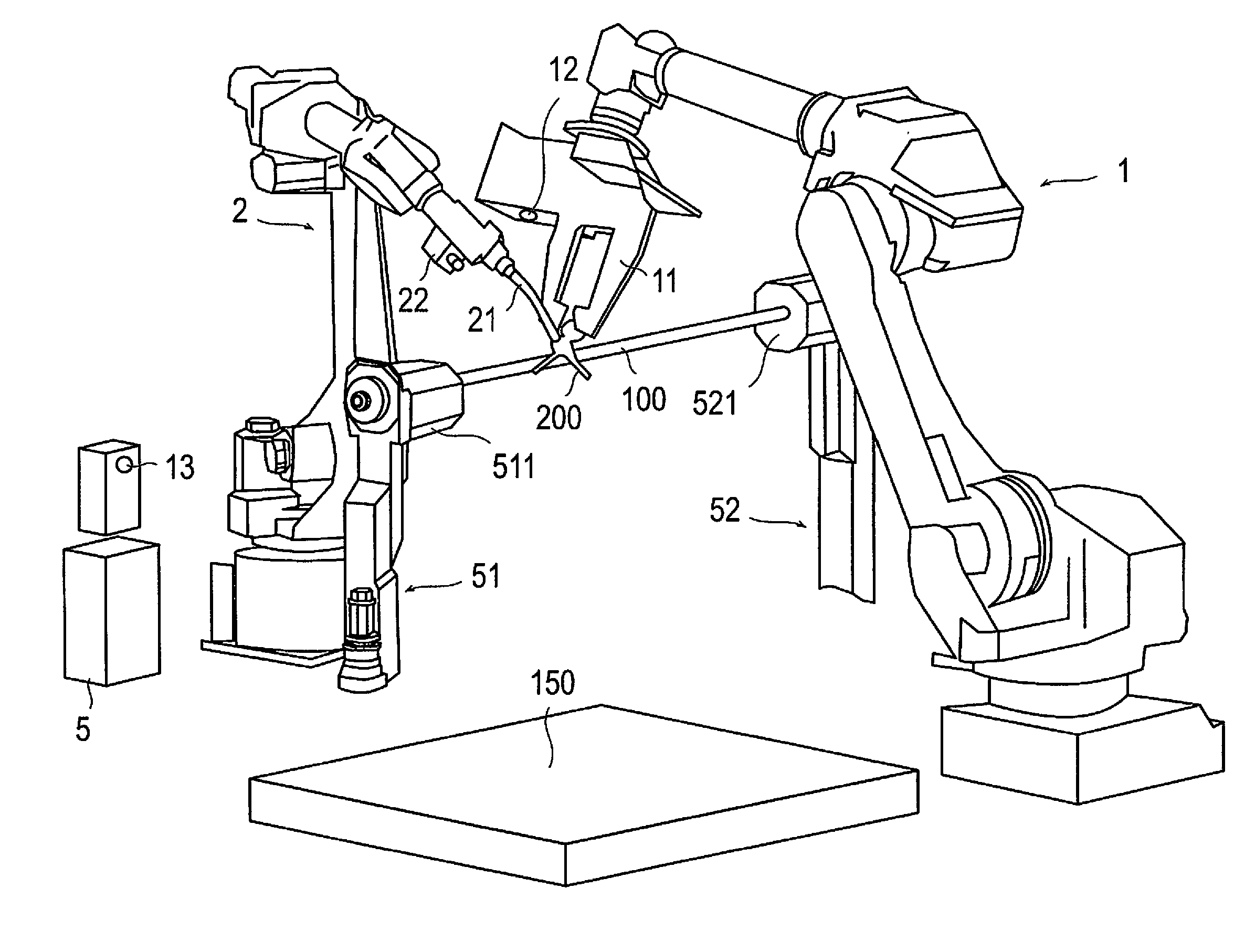
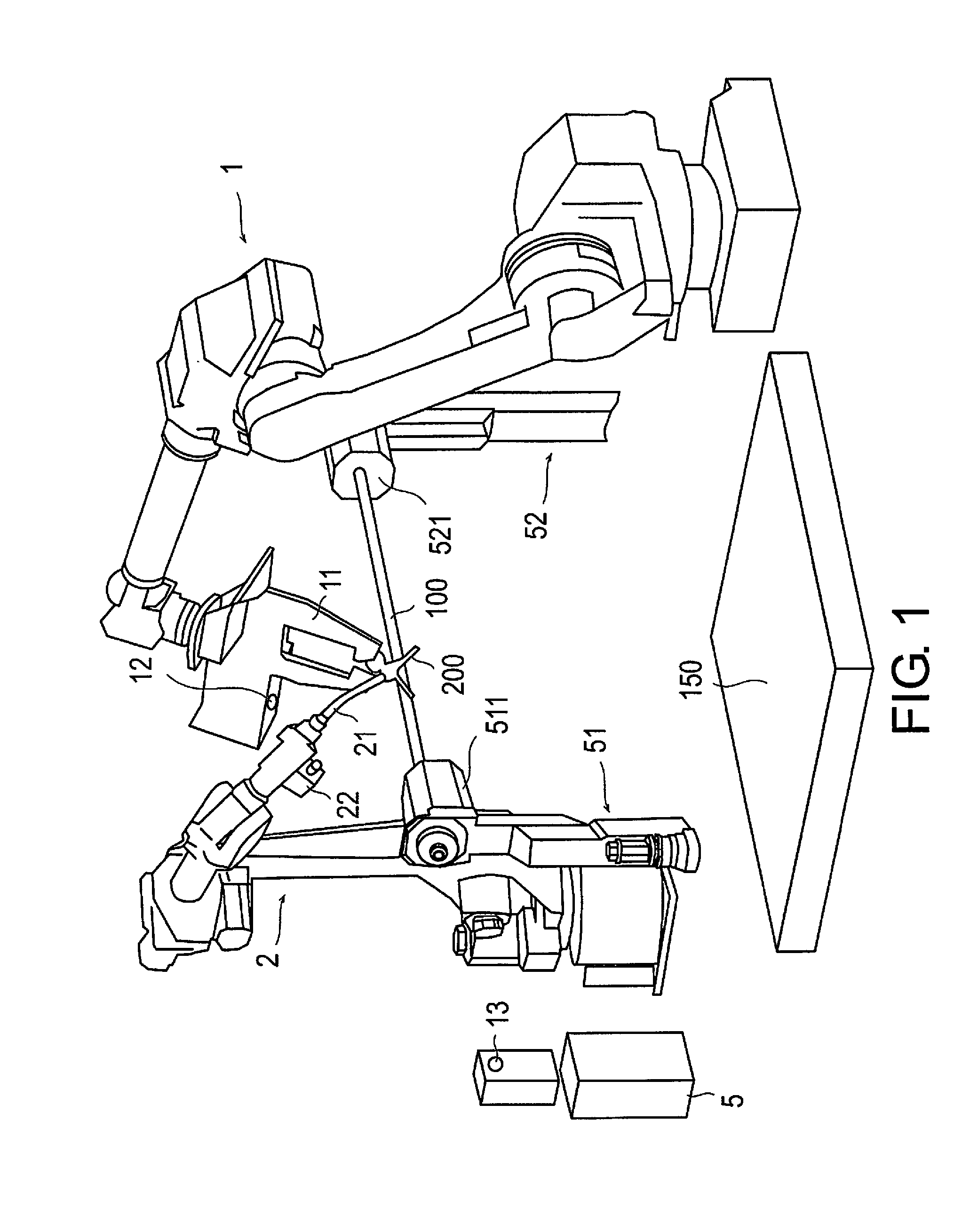
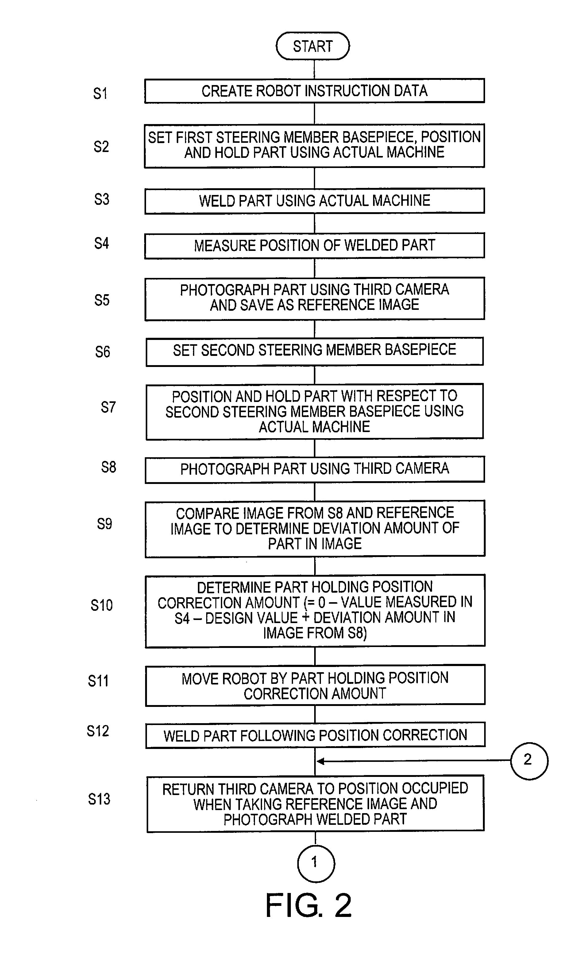
[0097]The foregoing embodiment features a process of creating robot instruction data (S1), setting a first steering member basepiece and positioning a part (S2), welding the positioned part (S3), measuring the position of the part (S4), storing a reference image (S5), setting a steering member basepiece (S6), positioning and holding a part (S7), photographing the part (S8), calculating the deviation amount of the part (S9), calculating a correction amount for the part (S10), correcting the position of the part (S11), welding (S12), photographing the welded part (S13), comparing the photograph image with the reference image (S14), updating the instruction data (S15), and storing a manufacturing reference image (S16).

[0098]However, the present invention is not limited to the foregoing embodiment, and the instruction data need not be updated. In other words, it is acceptable to perform the process from the creation of the robot instruction data (S1) to the...


PUM


Abstract

A manufacturing method for joining first and second members to create a joined piece using a robot with pre-inputted instruction data. The method includes operating the robot to hold the second member for joining to the first member and photographing the second member to obtain an image of the second member at the holding position; comparing the image to a reference image of a joining position of a reference second member joined to a reference first member; determining a deviation amount by which the holding position of the second member deviates from the joining position in the reference image; determining a correction amount for correcting the holding position of the second member is to be corrected in order to reduce the deviation amount of the holding position of the second member; correcting the holding position of the second member according to the correction amount, and then subsequently joining the first and second members.

Description

CROSS-REFERENCE TO RELATED APPLICATIONS[0001]This application is a U.S. National stage application of International Application No. PCT / JP2012 / 079838, filed Nov. 16, 2012, which claims priority to Japanese Patent Application No. 2011-250679 filed in Japan on Nov. 16, 2011, and Japanese Patent Application No. 2011-252064 filed in Japan on Nov. 16, 2012, the contents of which are hereby incorporated herein by reference.BACKGROUND[0002]1. Field of the Invention[0003]The present invention relates to a method and device for manufacturing a joined piece.[0004]2. Background Information[0005]Vehicle component parts are manufactured using various methods, such as casting, forging, and welding. For example, one type of vehicle component, a steering member (also known as a steering support member) features various parts, such as a steering supporter member or a harness attachment fixture, attached to a pipe-shaped member.[0006]As parts are primarily attached to these steering members via weldi...

Claims


Application Information

Patent Timeline
Patent Type & Authority Applications(United States)
IPC IPC(8): G05B19/402
CPCG05B19/402Y10S901/42Y10S901/47B25J9/1682B25J9/1697G05B2219/39131G05B2219/39132G05B2219/39393G05B2219/39397G05B2219/40611
Inventor HAYATA, JUNJITAKIZAWA, SATORU
Owner NISSAN MOTOR CO LTD
Why Eureka
Try Eureka