Laser marking device and method

a laser marking and engraving technology, applied in the field of laser marking and engraving systems and methods, can solve the problems of not being scalable, not cost effective, not cost effective, not having etc., and achieves the effect of not having a high maintenance cost, not requiring a lot of space, and being cost effective and flexibl

Inactive Publication Date: 2007-12-20
KNYSH ANDRIY +2
View PDF6 Cites 27 Cited by
  • Summary
  • Abstract
  • Description
  • Claims
  • Application Information

AI Technical Summary

Benefits of technology

[0016] An advantage of the present invention is to provide a laser marking system and method that is cost effective and flexibly to be adapted by any manufacturing environment.
[0017] Another advantage of the present invention is to provide a laser marking device that is very compact and does not require a lot of space on a factory floor.
[0018] Still another advantage of the present invention is to provide a laser marking device that does not have high cost of maintenance and is easily mounted on a robot arm for marking objects that would be difficult to access otherwise.
[0019] Still another advantage of the present invention is to provide a laser marking device and method that may simultaneously perform marking operations in several shops of a manufacturing facility through a local network using Ethernet or any of the Industrial Ethernet protocols, and between various manufacturing facilities located in different states and / or countries using the Internet.

Problems solved by technology

This system cannot be used on the factory floor autonomously, because the USB interface is a very short range bus and is a peer-to-peer interface, i.e. it always requires a master to be present on the bus.
Furthermore, in many cases, the USB interface is not acceptable on the factory floor.
These aforementioned prior art systems present numerous drawbacks and disadvantages.
One system always requires a host computer for each marking field with all the corresponding software, i.e. operating system and marking process control software, which is not cost effective, not scalable, not flexible in operation, and is non reliable.
Moreover, these prior art systems are not compact, take a lot of space on the factory floor, and have high cost of maintenance.
Furthermore, this system can not be easily mounted on a robot arm for marking objects that would be difficult to access otherwise.
It is very difficult to combine these systems into a distributed marking network thereby negatively impacting one of the main requirements in a modem laser marking industry.
Summarizing all the above, the main drawback of these marking systems is that it is very difficult to implement an efficient distributed networked marking system to mark on a plurality of spatially separated marking fields, stationary or on moving conveyors.
These prior art marking systems are unsuitable for industrial automation because of high cost, inflexibility, very long downtimes, but mostly because of difficulties in implementing real-time algorithms to manage the entire marking network and to control marking processes on each of the marking fields.
However, none of these prior art references discloses a system for distributed laser marking on a plurality of stationary or moving objects, and none of them provides a method for controlling the marking process in such a system.
Although the aforementioned prior art systems provide accurate control of the marking process on a single marking field, they are not adequate for marking on a plurality of marking fields and for controlling a large network of spatially distributed marking units, and hence they are not practically suitable for industrial automation and process control.

Method used


Image

  • Laser marking device and method
  • Laser marking device and method
  • Laser marking device and method

Examples


Embodiment Construction

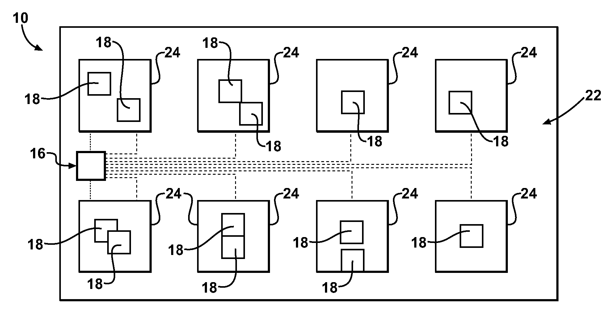
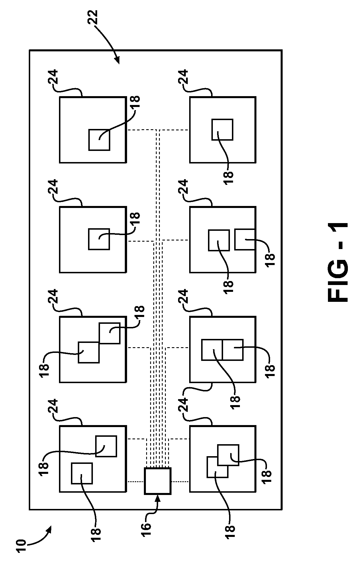
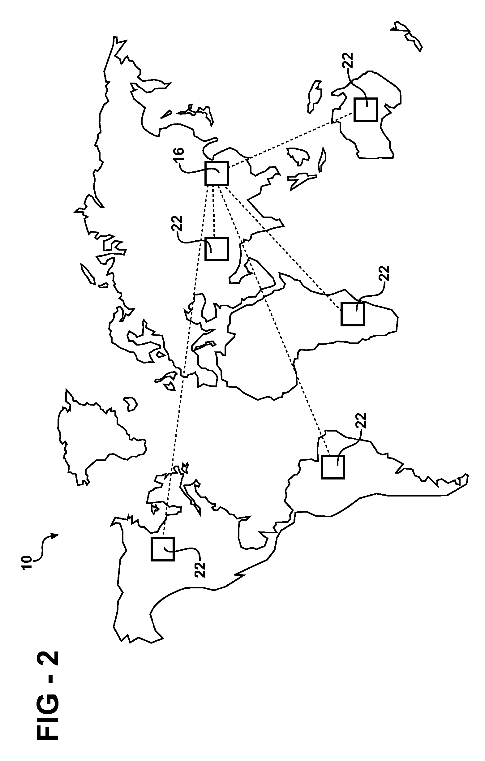
[0029] Referring now to Figures, wherein like numerals indicates like or corresponding parts, a laser marking system (the system) of the present invention is generally shown at 10 in FIGS. 1, 2, and 3. The system 10 presents a networked distributed scalable laser marking architecture for high-speed simultaneous or sequential marking on a plurality of workpieces or parts, generally indicated at 12 in FIG. 3. Each part 12 has at least one ID tag associated with it, generally indicated at 15 in FIG. 3, for storing at least one of marking content and part's type information. Each ID tag 15 is further defined as at least one of RFID, magnetic, capacitive, and barcode tags attached to or incorporated into part 12, without limiting the scope of the present invention. The system 10 includes a main controller 16 and a network of distributed marking units 18 networkingly connected with one another and the main controller 16 by Ethernet, Industrial Ethernet, Internet, and / or wireless protocols...


PUM

PropertyMeasurementUnit
speedaaaaaaaaaa
magneticaaaaaaaaaa
motion speedsaaaaaaaaaa

Abstract

The laser marking device of the present invention utilizes a networked distributed scalable architecture for high-speed simultaneous or sequential marking on a plurality of stationary or moving objects. A plurality of marking units and a controller are connected with one another through a network interface. The controller generates commands and data for the entire marking process and performs general flow control.

Description

RELATED APPLICATIONS [0001] This application claims priority to U.S. Provisional Patent Application Ser. No. 60 / 814,738 filed Jun. 19, 2006 incorporated herewith in its entirety.FIELD OF THE INVENTION [0002] The present invention relates generally to laser marking and engraving systems and methods. BACKGROUND OF THE INVENTION [0003] Laser marking is state-of-the-art technology, which applies computer-generated text, graphics, and machine-readable code on various workpieces, such as, for example, metal, plastic, and elastomeric materials widely used in modern industries. As compared with prior art marking technologies, modern laser marking technology delivers a powerful combination of reduced operating costs and high throughput under complete computer control. There are numerous reasons why the laser marking technology is so popular today. One reason relates to extremely durable method of marking an object. Another reason relates to the fact that lasers produce indelible marks on var...

Claims


Application Information

Patent Timeline
Patent Type & Authority Applications(United States)
IPC IPC(8): B23K26/36B23K37/00
CPCG05B19/41815Y02P90/02
Inventor KNYSH, ANDRIYMOSHKOV, ALEXEYKRIVORUCHKO, NIKOLAI
Owner KNYSH ANDRIY
Why Eureka
Try Eureka