Spot-type disc brake with a spring assembly for a brake pad

a brake pad and spring assembly technology, applied in the field of vehicle brakes, can solve the problems of affecting the functioning affecting the operation of the brake pad, and the possibility of removing and losing the reset spring,

Inactive Publication Date: 2005-07-26
CONTINENTAL TEVES AG & CO OHG
View PDF41 Cites 27 Cited by
  • Summary
  • Abstract
  • Description
  • Claims
  • Application Information

AI Technical Summary

Problems solved by technology

The resetting springs are anchored only insufficiently in the disc brake so that the resetting springs may easily be detached and lost, especially when exposed to vibrations.
However, this necessitates an undesirable additional fastening means for each resetting spring.
In addition, the use of two resetting springs basically involves the risk that in the event of failure of one of the resetting springs there will occur an inclined position of a brake pad which impairs functioning.

Method used


Image

  • Spot-type disc brake with a spring assembly for a brake pad
  • Spot-type disc brake with a spring assembly for a brake pad
  • Spot-type disc brake with a spring assembly for a brake pad

Examples


Embodiment Construction

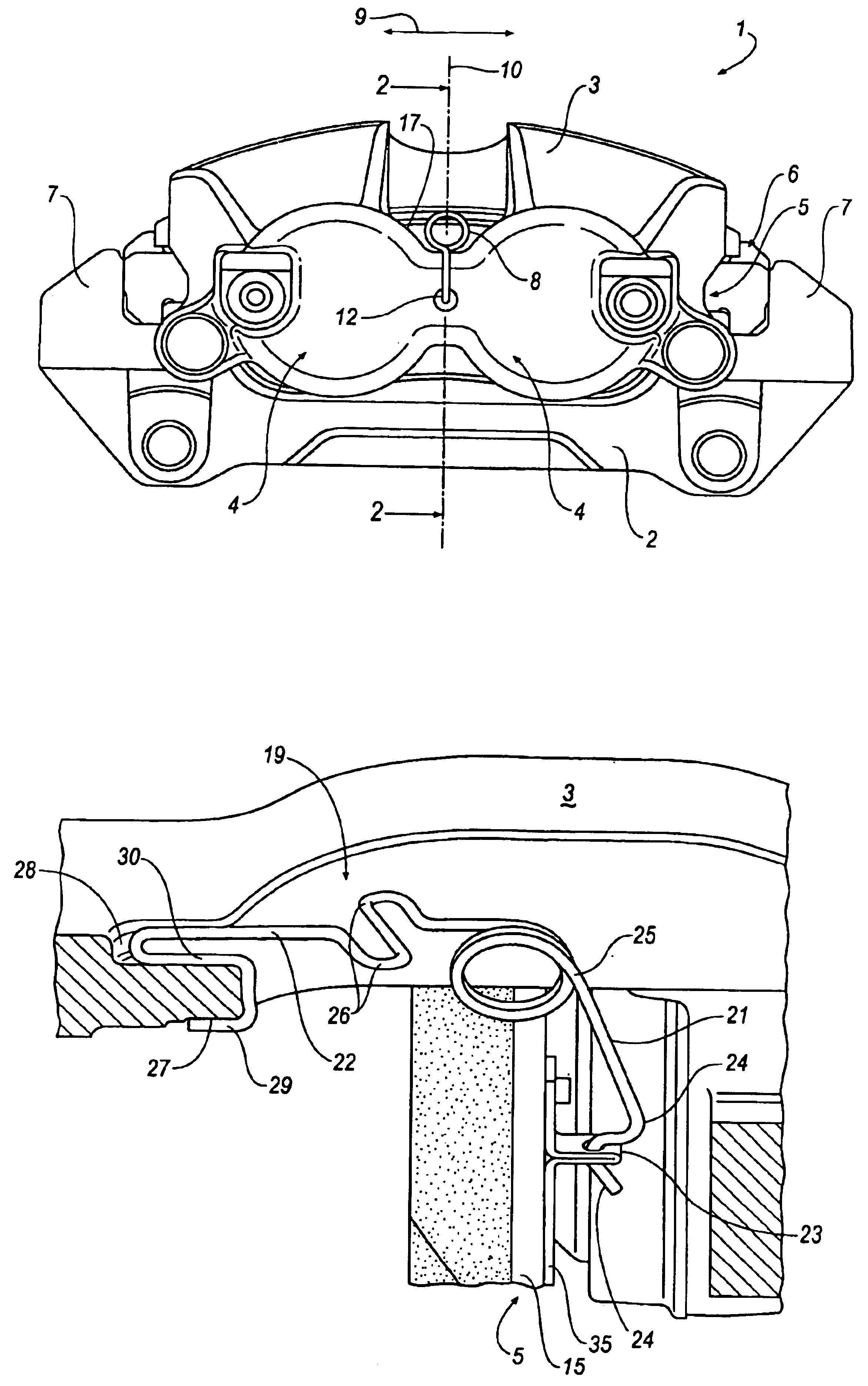
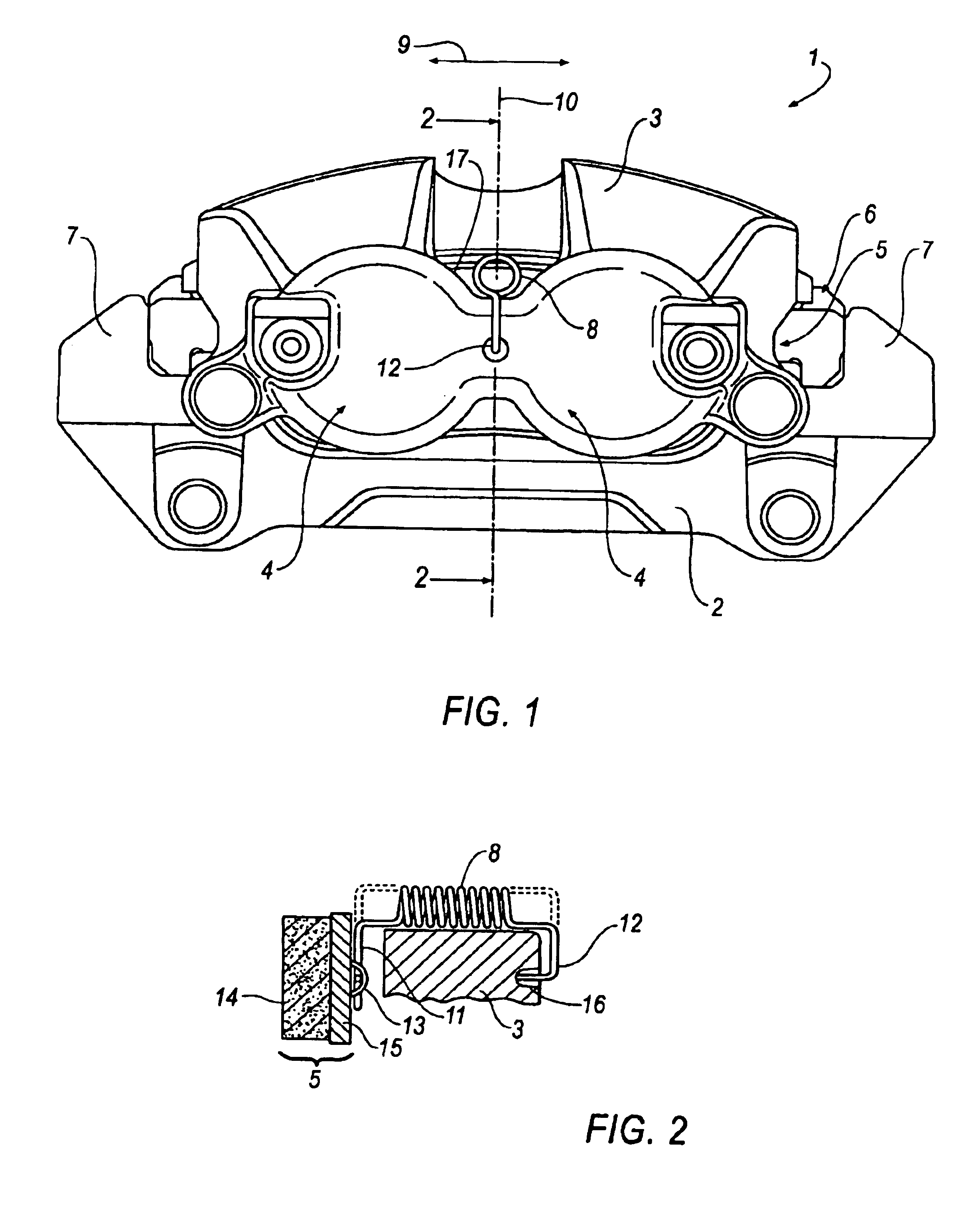
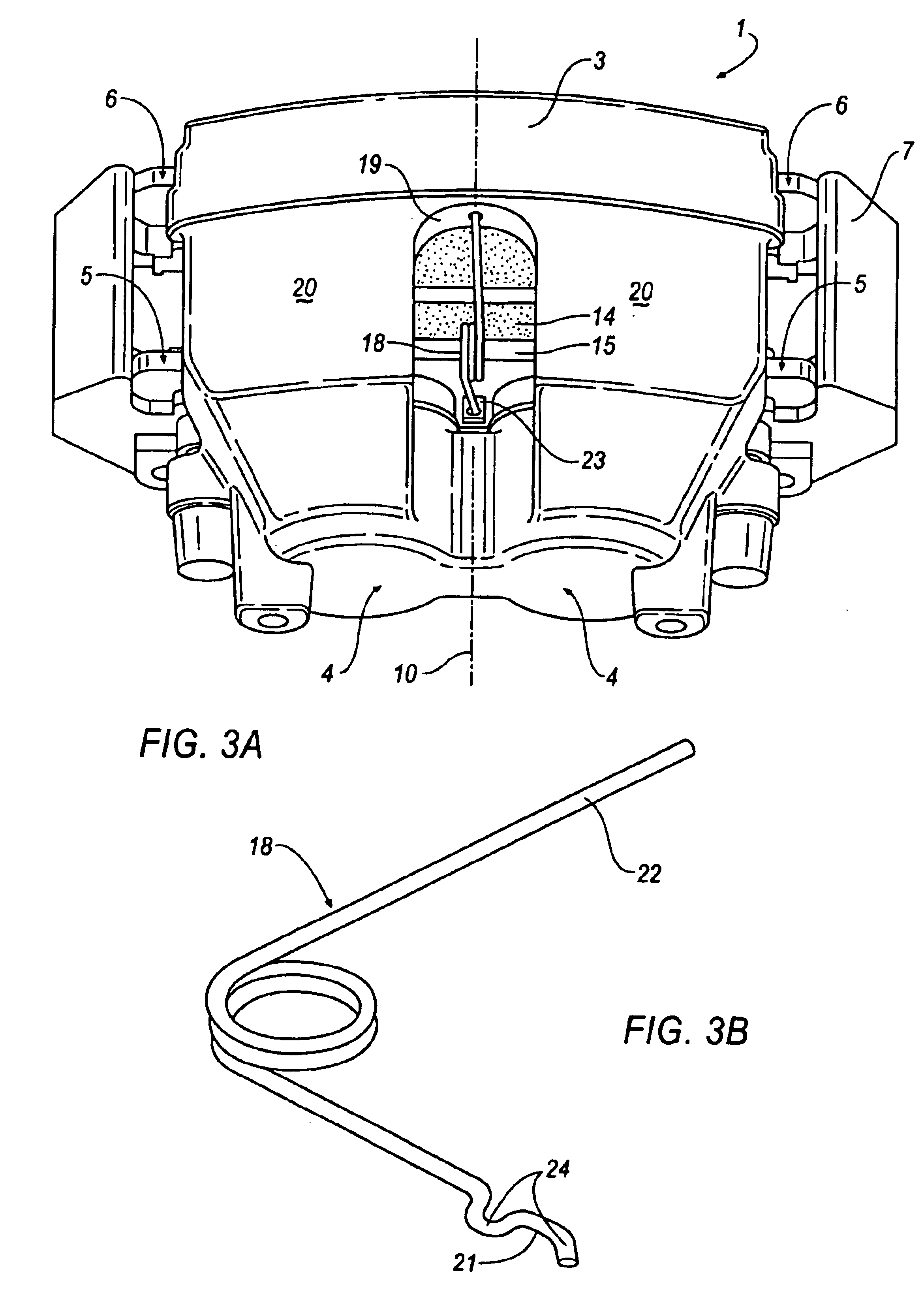
[0017]The spot-type disc brake 1 of an automotive vehicle shown in the Figures comprises a brake holder 2 mounted fast on the vehicle and a brake housing 3 slidably mounted on the brake holder 2. More particularly, housing 3 is designed as a brake caliper straddling a brake disc (not shown). On one side of the brake disc, the brake housing 3 includes at least one actuating device 4 for the application of brake pads 5, 6 arranged on either side of the brake disc. Each brake pad 5, 6 includes a friction lining 14 and a carrier plate 15. During a brake application, a first brake pad 5 is applied by the actuating device 4 directly and a second brake pad 6 is pressed due to an axial shift of the brake housing 3 indirectly against the brake disc. In the Figures, embodiments of the brake housing with two actuating devices 4 are shown which are designed as a hydraulic piston-and-cylinder unit. It is of course also possible to use pneumatically, electrically, or mechanically acting actuating...


PUM


Abstract

The present invention relates to a spot-type disc brake with a brake housing straddling a brake disc, with at least one brake pad that is arranged in the brake housing so as to be slidable in the actuating direction and cooperates tribologically with the brake disc upon brake application, with at least one actuating device arranged in the brake housing to apply an actuating force to the brake pad, and with a spring assembly for the active adjustment of a clearance between the brake pad and the brake disc after brake application. To simplify the configuration of the spring assembly, the spring assembly comprises exactly one spring which is secured detachably in the spot-type disc brake and is supported on the brake pad and on the brake housing. A spring of this type is arranged advantageously symmetrically within the brake housing to prevent an undesirable inclined positioning of the brake pads.

Description

TECHNICAL FIELD[0001]The present invention generally relates to vehicle brakes, and more particularly relates to a spot-type disc brake with a spring assembly for the active adjustment of a clearance between a brake pad and a brake disc.BACKGROUND OF THE INVENTION[0002]DE 31 30 185 A1 discloses a disc brake with resetting springs. The disc brake includes two resetting springs spaced in a circumferential direction and abutting with free spring legs on brake pads arranged on either side of the brake disc. The brake pads are lifted from the brake disc after a brake operation due to the spreading effect of the spring legs. The springs are compressed between a brake holder, a brake caliper and the brake pads in a first assembly. The resetting springs are anchored only insufficiently in the disc brake so that the resetting springs may easily be detached and lost, especially when exposed to vibrations. In a second design, the resetting springs are screwed to the disc brake. However, this n...

Claims


Application Information

Patent Timeline
Patent Type & Authority Patents(United States)
IPC IPC(8): F16D65/092F16D65/097
CPCF16D65/097F16D65/0975F16D65/0979
Inventor BURGDORF, JOCHENKAST, HELMUTTHIEL, RUDOLFSUNDHEIM, RALFLEHMANN, KURT
Owner CONTINENTAL TEVES AG & CO OHG
Why Eureka
Try Eureka