Panel fastening rivet mechanism

a rivet mechanism and rivet technology, applied in the direction of fastening means, screws, threaded fasteners, etc., can solve the problems of limited adaptability of clips, and achieve the effect of reducing manufacturing and assembly costs and inventory requirements

Active Publication Date: 2014-10-23
ILLINOIS TOOL WORKS INC
View PDF20 Cites 5 Cited by
  • Summary
  • Abstract
  • Description
  • Claims
  • Application Information

AI Technical Summary

Benefits of technology

[0007]It has been determined that a clip design capable of panel securement over a wide range of pilot hole dimensions and panel thickness is valuable to the marketplace. A given clip suitable for a wide range of applications reduces manufacturing and assembly costs, and inventory requirements.

Problems solved by technology

More particularly, it relates to such a clip suitable for joining such panels in instances where pilot holes in each panel are of different diameter or present excessive clearance with the fastener leg.
As a result, versatility of the clips may be limited by the size of, and clearance with, the pilot holes that receive them.

Method used


Image

  • Panel fastening rivet mechanism
  • Panel fastening rivet mechanism
  • Panel fastening rivet mechanism

Examples


Embodiment Construction

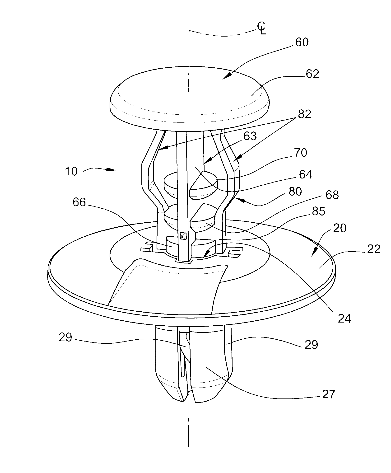
[0019]Turning now to the drawings, there is illustrated in FIGS. 1 to 7 a panel rivet assembly or retention clip in accordance with the present disclosure. As seen in FIG. 4, the panel rivet assembly 10 is employed to join components of a structure, here illustrated as two separate panels, 11 and 12. Taken as exemplary, panel 11 may be a sheet metal component such as an automotive hood panel. Panel 12 may be a relatively flexible component such as a composite sound deadening pad or the like.

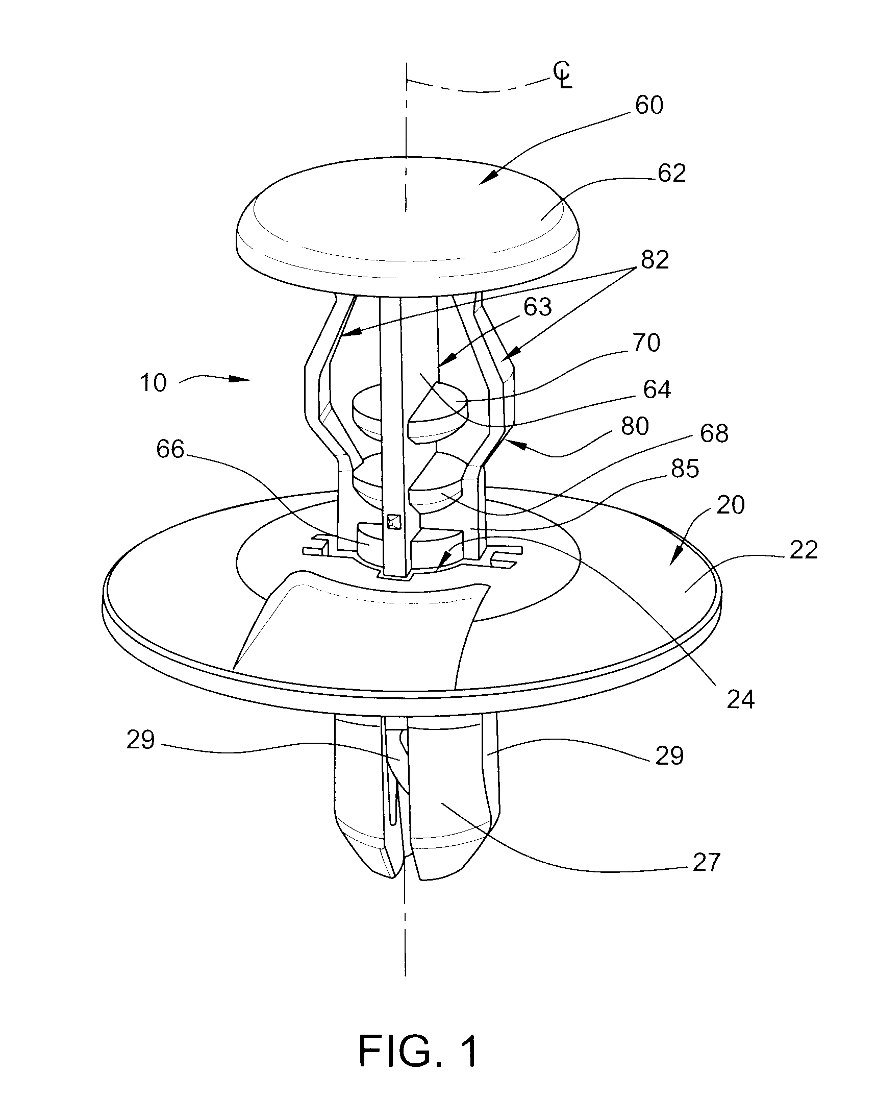
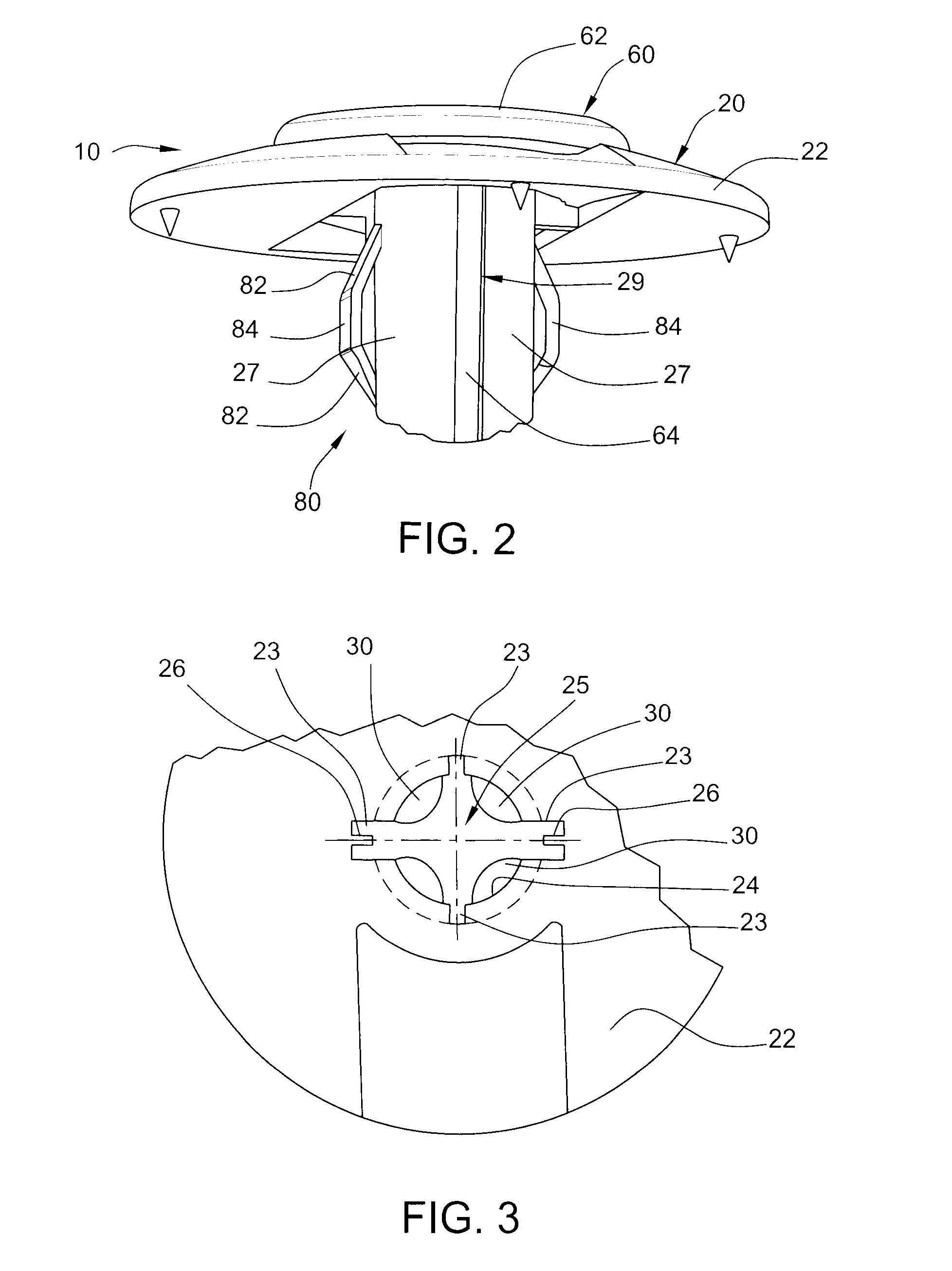
[0020]As illustrated in FIG. 3, the panel 11 has one or more pilot holes 13. Panel 12 has one or more pilot holes 14 aligned with the pilot holes in the sheet metal panel 11. A fastening rivet 10 is used at each set of pilot holes to connect the separate panels. In the illustrated installation of FIG. 4, the pilot holes 13 and 14 are larger in diameter than the diameter of the insertable leg of the body 20 of the retention clip assembly 10.

[0021]FIG. 1 shows the clip assembly 10 comprising two co...


PUM

PropertyMeasurementUnit
flexibleaaaaaaaaaa
diameteraaaaaaaaaa
top angleaaaaaaaaaa

Abstract

A retention clip assembly to join individual panels with aligned pilot holes comprises a body having an enlarged flange and a generally cylindrical leg defined by a plurality of spaced leg segments surrounding a pin insertion hole. The leg segments are separated by spaced slits and define a central passage. A pin having an enlarged head and an elongate shaft is slidable in the central passage. It engages cam projections on the interiors of the leg segments and expands the segments to secure the body to the panels. The pin includes flexible fingers having radially outer surfaces spaced apart a distance greater than the body leg deformable toward the pin shaft. The flexible fingers pass through the body flange and expand after surpassing the pilot holes in the panels. The flexible fingers slide in diametrically opposed slits, contact the edges of the pilot holes and stabilize the clip assembly within the pilot holes.

Description

CROSS-REFERENCE TO RELATED APPLICATION[0001]This application claims priority pursuant to Title 35 USC §119(e) to U.S. Provisional Application Ser. No. 61 / 558,917, filed Nov. 11, 2011, entitled “Panel Fastening Rivet Mechanism,” the entire specification and drawings of which are hereby incorporated by reference herein as if fully set forth.BACKGROUND[0002]This disclosure relates to a retention clip to fasten two panels together to retain one to the other. More particularly, it relates to such a clip suitable for joining such panels in instances where pilot holes in each panel are of different diameter or present excessive clearance with the fastener leg.[0003]U.S. Pat. No. 5,632,581 entitled “Clip” issued Mar. 27, 1997 and assigned to Illinois Tool Works, Inc., Glenview, Ill., discloses a clip useful to join two panels. It is used in assembly of various panel components and is particularly suitable for assembly of panel components in the automotive industry. The entire specification ...

Claims


Application Information

Patent Timeline
Patent Type & Authority Applications(United States)
IPC IPC(8): B21J15/04F16B19/10
CPCF16B19/1027B21J15/041F16B19/1081Y10T29/49956
Inventor KANIE, HIDEKIOMORI, YASUOMIJENSEN, JESSE L.
Owner ILLINOIS TOOL WORKS INC
Why Eureka
Try Eureka